26.07.2001 ActIPret
Interpreting and Understanding Activities of Expert Operators for Teaching and Education
The objective of ActIPret is to develope a cognitive vision methodology that interprets and records the activities of people handling tools. Focus is on active observation and interpretation of activities, on parsing the sequences into constituent behaviour elements, and on extracting the essential activities and their functional dependence. By providing this functionality ActIPret will enable observation of experts executing intricate tasks such as repairing machines and maintaining plants. The expert activities are interpreted and stored using natural language expressions in an activity plan. The activity plan is an indexed manual in the form of 3D reconstructed scenes, which can be replayed at any time and location to many users using Augmented Reality equipment.
![]()
Please visit the German-language site for more information.
26.07.2000 RobVision
Manouver a walking robot into ship sections using vision
Industries using a CAD-system to design parts or working areas need a means of feedback to enable a comparison of designed and manufactured structures. Using vision, based on the CAD information, is an effective tool to establish this link. For example, the autonomy of a robotic vehicle is needed in several applications in building and inspecting of large structures, such as ship bodies. The navigation of a walking robot will be demonstrated using this vision tool. Furthermore, the vision tool can be used for the task of dimensional measurements of parts. The project costs over a period of two years are 1125 kECU including 750 kECU funding from the CEC.
Objectives
This project develops a vision system that finds and measures the location of 3D structures with respect to a CAD-model. The integration of a CAD-model to visual measurement and direct feedback of measurement results is a key aspect. The objective is to render visual processing robust to deviations in parts and environmental conditions. To achieve this goal a technique is developed that integrates different cues of images to obtain confidence of the measurement result.
Approach
Reliability is tackled by developing a theory of robust visual recognition by integrating redundant low level image cues and sparse high level object knowledge. Image cues and object knowledge are exploited and integrated both at a local and global level. For the extraction of basic visual cues independent and complimentary modules are envisaged. The modularity of the toolbox is the basis for integrating the acquisition of visual information with tools of the control and engineering process.
Demonstration
The project focuses on using the vision system for guiding a robotic vehicle to enable it to navigate and position itself in order to deliver work packages for inspection, welding and other tasks for the structure/body of a large vessel during production. The final demonstration will see the walking robot enter and climb the vessel structure..
Exploitation/Results
The ROBVISION project will achieve the following results:
- a tool to measure 3D object position and orientation with the aid of a CAD-model,
- a toolbox of modules for cue extraction from images and models and a theory to integrate these cues to obtain robustness and reliability,
- a theory of integrating object knowledge from CAD-models for cue extraction to increase the reliability of cue and therefore object detection, and
- the integrated vision system capable of providing adequate information to guide an advanced robotic vehicle through a complex structure.
The potential uses for such a tool are quite diverse. The principal capability is to use a CAD-model to find features in images and to return the position and orientation measured back into the CAD-model.
Consortium
- INFA – Institute of Flexible Automation, A
- Odense – Odense Steel Shipyard Ltd., DK
- Portech – Portsmouth Technology Consultants Limited, GB
- Aalborg – Aalborg University, Department of Production, DK
- DIST – Lab for Integrated Advanced Robotics, IT
26.07.2000 FlexPaint
The objective of the project FlexPaint is to provide a system for automatic spray painting. The goal is to paint all arriving parts and to reach a batch size of one. The final solution will make it possible to paint any arriving part in the paint cell without the need for models or other data. The final product will provide a fully self-contained solution to the spray painting problem. The project is funded by the European commission with 1.1 MEuro and will last until July 2002 (partner).
The technical problems are solved by the academic partners of this project. They proposed and already tested in prototypes the following approach:
- Sensing the geometry of the parts with one or more range sensors
- Extracting the geometry for painting from the sensor data
- Using the geometry to determine a painting trajectory
- Generating the robot program for the trajectories with a planner that also avoids collisions
All these steps will be executed automatically such that interference of operators is not needed and all arriving parts can be painted. The steps will be executed in real-time. The cycle time is selected such that the sensing cell can be placed directly in front of the painting.
12.06.2000 Tracking Evaluation
A Methodology for Performance Evaluation of Model-based Tracking*
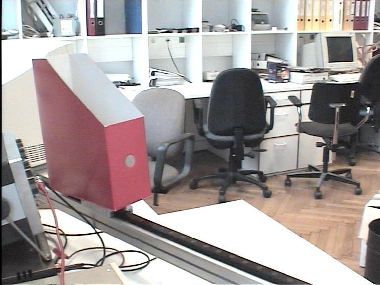
Model-based object tracking has become an important means to perform robot navigation and visual servoing tasks. Until today it is still difficult to define robustness parameters which allow the direct comparison of tracking approaches and that provide objective measures of progress achieved with respect to robustness. Particularly, extensive algorithm testing is an obstacle because of the difficulty to extract ground truth. In this paper, we propose a methodology based on the evaluation of a video database which contains real-world image sequences with well-defined movements of modeled objects. It is suggested to set up and extend this database as a benchmark. Moreover, tests of the performance evaluation of the tracking system V4R (Vision for Robotics) are presented.
Video database of real-world image sequences
First image preview | Sequence description | Sequence zipped
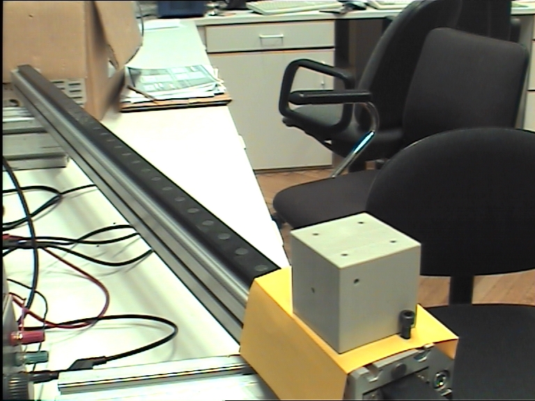 Gray cube moving backwards left | gray_cube1.zip
 Gray cube moving backwards left | gray_cube2.zip
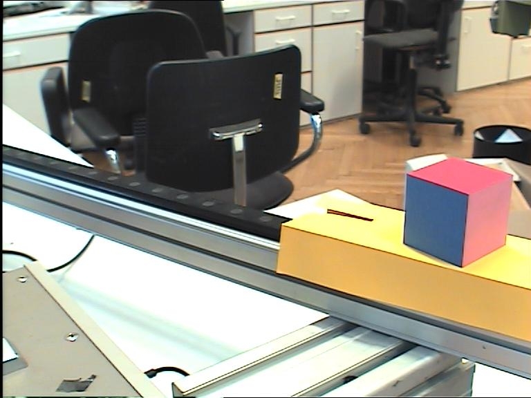 Color cube moving backwards left | color_cube3.zip
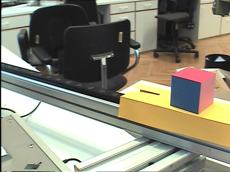 Color cube moving backwards left | color_cube4.zip
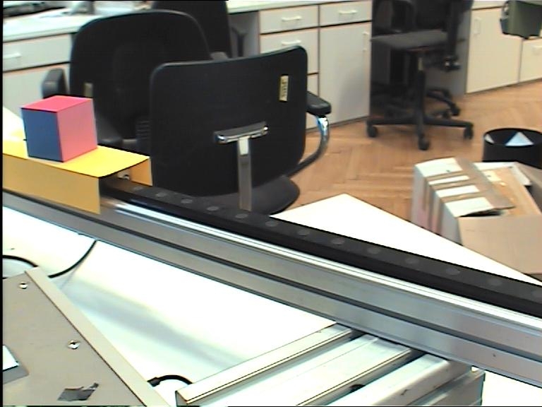 Color cube moving towards right | color_cube5.zip
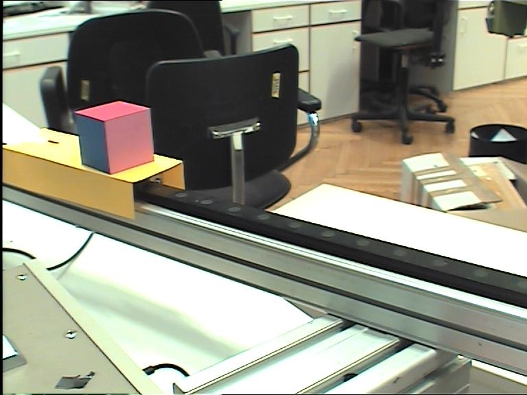 Color cube moving towards right | color_cube6.zip
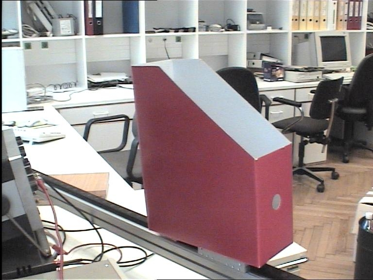 Magazine box moving backwards left | magazine_box7.zip
Magazine box moving backwards left | magazine_box8.zip
 Magazine box moving towards right | magazine_box9.zip
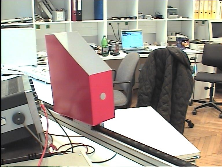 Magazine box moving towards right | magazine_box10.zip
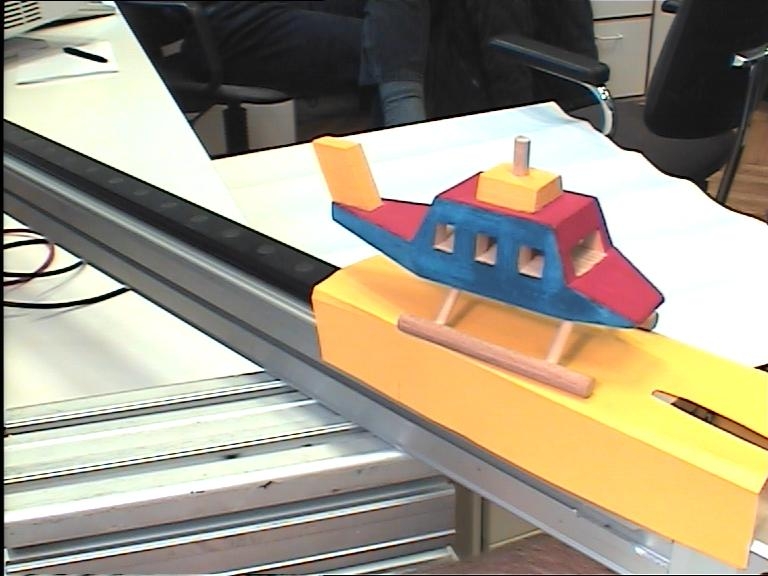 Toy copter moving backwards left | toy_copter11.zip
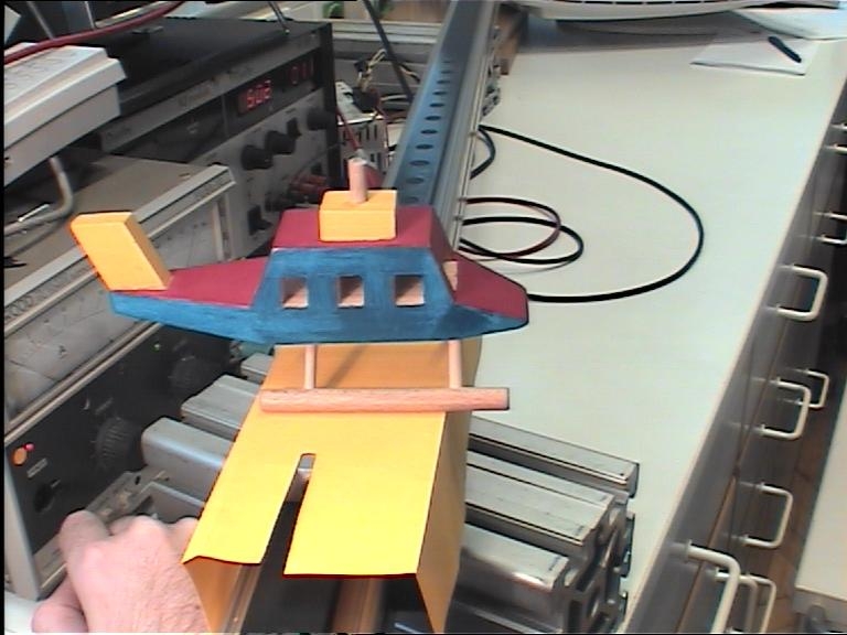 Toy copter moving backwards right | toy_copter12.zip
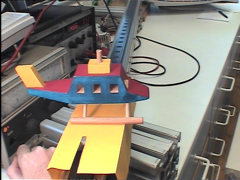 Toy copter moving backwards right | toy_copter13.zip
* This work has been supported by the EU-Project ActIPret under grant IST-2001-32184.
12.06.2000 TOS
Trainings Optimierungs System
- Ballverfolgung
- Stereo-Bildverarbeitung
- statistische Auswertung
Beschreibung
Das Trainings-Optimierungs-System eignet sich für:
Automatisches Erfassen der Ballflugbahn mit PC-gesteuertem Zweikamerasystem Bestimmung der Ballposition auf 5cm genau und Bestimmung der Schußschärfe auf ± 1 % der Ballgeschwindigkeit.