Ball on Ball
Project focus
- Modelling of a Ball on Ball Setup
- Control of a Ball on Ball Setup
- Camera based control
Description
Vision-based measurement methods are becoming increasingly important in automation technology. Well-known examples are autonomous vehicles that navigate through the environment using a variety of imaging sensors, or robots that detect if someone has entered the working area using a camera. Nowadays the needed computing power for real-time image processing is readily-available which opens up new possibilities to use vision-based measurement methods in industrial automation. In this project a Ball-on-Ball control setup with vision-based position measurement is designed, simulated and built to demonstrate the capabilities of imaging techniques. Before the setup is implemented a nonlinear mathematical model of the whole setup is derived and simulations of the system behaviour are done. The control and the image processing is done on an industrial standard PLC. For comparison a second measurement method using laser distance sensors is also implemented. The residual error and the disturbance reaction of both measurement methods are analyzed and compared using different controllers and sample times. Finally a trajectory following for the upper ball is implemented.
Automation and Industrial Control Systems
To actuate the lower ball three omniwheels are used. Each omniwheel is driven by Beckhoff DC servo motor with a gearbox in between. The Control of the motor current and the motor speed is done directly on the motor controllers. That means, that the PLC calculates the speeds needed for all three drives and hands them over to the controllers. The position mesaurement of the upper ball can ether be done by two triangulation sensores or by a camera on top of the upper ball. For robustness reasons of detecting the upper ball the recorded image is transformed into the hue, saturation, and value color space. Due to this transformation the dependency of the illumination can be suppressed. The image aquisition and calculation of the upper ball position is done entirely on the PLC.
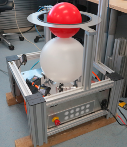
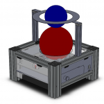
Complete ball on ball setup
Video 1: Trajectory following of the upper ball seen from the cameras perspective.
The desired trajectory is a circle.
Applications
- Camera based control
Related Publications
- C:. Zech, Development, assembly and implementation of a ball on ball control setup, 2017.
[BibTex]@MastersThesis{TUW-311819, Title = {Development, assembly and implementation of a ball on ball control setup}, Author = {C: Zech}, School = {E376}, Year = {2017} }
Project partners
Funding
Contact
Dipl.-Ing. Matthias BiblUniv.-Prof. Dipl.-Ing. Dr.sc.techn. Georg Schitter
Project Staff
Dipl.-Ing. Matthias BiblDipl.-Ing. Christoph Zech