
Scanning optical point- and line-sensor (SOS)
Project focus
- Development of scanning systems with different optical sensors for 3D imaging
- High-speed, high-precision motion control of scanners for imaging
- Data acquisition system to accurately reconstruct 3D images
Description
In order to optimize production settings and inspect products at factories for high productivity and reliability, surface properties of the products can be evaluated by three dimensional (3D) measurements. For these applications, optical sensors are ideal for their high-speed non-contact and accurate measurements, such as laser triangulation sensors and polychromatic confocal sensors for displacement measurement, as well as colorimeters and spectrophotometers for color sensing, as shown in Fig. 1. To generate 3D measurement data, such sensors are moved with respect to the products for scanning. However, currently used methods have limited performance on measurement rage, scanning speed, motion precision, or flexibility.
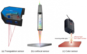
Different types of optical sensors targeted for the scanning optical-point and -line systems.
To overcome the limitation for better productivity and reliability of production in this project, a rotating or steering mirror scans the sensor’s optical point or line over a product surface, targeting triangulation, confocal, and color sensors.
Scanning triangulation sensor system
Laser triangulation sensors are one of the most commonly used optical sensors in dimensional metrology and quality control tasks, due to their large measurement range as well as their high resolution. In order to precisely obtain the distance between sample and sensor, the diffusely scattered laser light spot from the sample must be projected sharply onto the detector, which can only be realized by fulfilling the imaging condition. Figure 2 shows an optical scanning triangulation sensor system, which manipulates only the illumination path of the sensor, such that a fast steering mirror (FSM) with a small aperture size can be used, enabling a high scan speed. However, the imaging condition could be violated, through the scanning motion. By placing the FSM on the intersection line of the lens and detector plane, the imaging condition is satisfied at each measurement point. As can be observed in Fig. 2(a), the position of the intersection line can be changed by inserting a static mirror in the optical path, such that the FSM can be placed elsewhere.
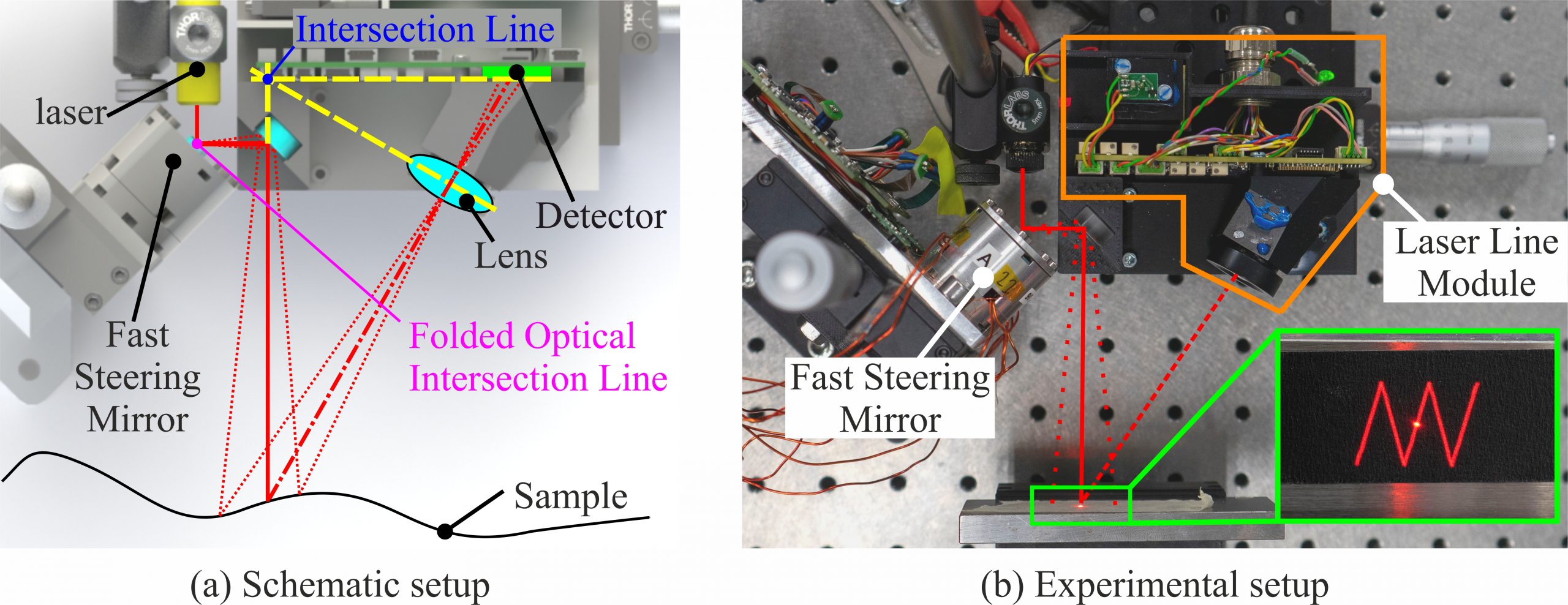
Schematic (a) and experimental (b) setup of the scanning point sensor system. The illumination path is manipulated with a compact HRA FSM at the intersection line to maintain the imaging condition.
To scan the area of interest, appropriate scan patterns are required. Most commonly raster scan trajectories are employed, which generate an image with a uniform spatial resolution. Lately Lissajous-based scan trajectories have been utilized for precision scanning systems. Due to the multi-resolution property, an early overview of the complete scan area is generated and continuously refined. Depending on the application, the raster or Lissajous scan trajectory prove advantageous.
Figure 3 depicts the measurement results of the optical scanning system and a conventional mechanical scanning system. The measured height of the hollow cylinder is comparable between the two scanning methods (optical 4.44 mm, mechanical 4.493 mm). However, the measurement time can be reduced from 67 minutes to 10 seconds through the optical scan, which is reduction by a of 400.
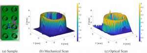
Measurement result. (a) shows the sample and selected area of interest. (b) and (c) show the measured surface profile of the mechanical and optical scanning triangulation sensor system.
Scanning chromatic confocal sensor system
Fig. 4 shows a photograph of a scanning system for an off-the-shelf chromatic confocal displacement sensor, which is well-calibrated and reliable. The optical point of the sensor scans a sample for topography imaging. For raster scanning of the optical point, the sample is moved by a linear stage. Because its mover is relatively large and heavy, dependent on the sample, such a conventional method restricts the achievable scanning speed. As a result, a long measurement time is typically required. Therefore, for the fast lateral scanning axis of raster scanning, the optical point is scanned by a galvanometer scanner that rotates a mirror. This enables to increase the scanning speed by moving neither the sensor nor the sample but the optical path along the fast scan axis.
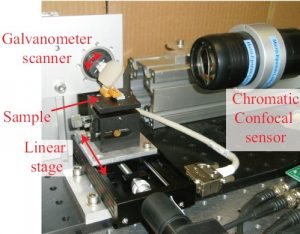
Scanning system that integrates an off-the-shelf chromatic confocal displacement sensor [S. Ito et al., in Proceedings of Summer Topical Meeting, Advancing Precision in Additive Manufacturing, p. 226–231, 2018].
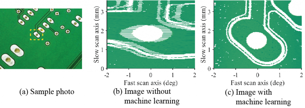
Sample and reconstructed images: (a) photograph of a sample and reconstructed images (b) without and (c) with machine learning [E. Csencsics et al., E&I, 135(6), p. 382–388, 2018].
Scanning color sensor system
To correctly obtain the color of a surface, a precise alignment between the color sensor and the sample is necessary. State of the art color sensors are ether contact based, which could impair the surface of the sample during the measurement, or non-contact, such that several additional external sensors are necessary to align the sensor with respect to the sample. By scanning the optical path of a non-contact color sensor the orientation between sensor and sample can be changed. Figure 6 depicts the experimental setup of the scanning color sensor system, which consists out of a fast steering mirror and a color sensor. To manipulate the distance between the sample and sensor a motorized stage is used.
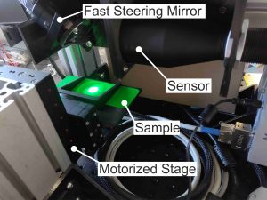
The optical path of an off-the-shelf color sensor is scanned by a fast steering mirror.
The measurement result of a RAL color card (RAL5026) is depicted in Fig. 7. As can be observed the brightness value L* has an extrema at an angular position of θx = 0° and θy = 0°, which corresponds to the correct orientation between sensor and sample. The measurement results of a* and b* can not be used for the alignment, since the position of their extrema’s is influenced by the measured color. Figure 7 also depicts the measurement results for various distances between sensor and sample. The brightness value L* has a maximum at a distance of z = 33 mm, which corresponds to the correct distance between sensor and sample, such that the correct alignment can be observed without any additional sensors.
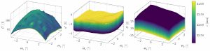
Measurement results of a RAL color card for various positions and orientations. The correct alignment can be observed with the brightness value L*.
Applications
- In-line metrology
- Product inspection
- 3D imaging
Related publications
- J. Schlarp, E. Csencsics, and G. Schitter, Design and evaluation of an integrated scanning laser triangulation sensor, Mechatronics, vol. 72, p. 102453, 2020.
[BibTex] [Download]@article{TUW-290944, author = {Schlarp, Johannes and Csencsics, Ernst and Schitter, Georg}, title = {Design and evaluation of an integrated scanning laser triangulation sensor}, journal = {Mechatronics}, year = {2020}, volume = {72}, pages = {102453}, doi = {10.1016/j.mechatronics.2020.102453}, keywords = {Optical sensing and sensors, 3D sensorLaser sensor, Fast steering mirror, System analysis and design} }
- J. Schlarp, E. Csencsics, and G. Schitter, Optical scanning of a laser triangulation sensor for 3D imaging, IEEE Transactions on Instrumentation and Measurement, vol. 69, iss. 6, p. 3606–3613, 2020.
[BibTex] [Download]@article{TUW-282494, author = {Schlarp, Johannes and Csencsics, Ernst and Schitter, Georg}, title = {Optical scanning of a laser triangulation sensor for 3D imaging}, journal = {IEEE Transactions on Instrumentation and Measurement}, year = {2020}, volume = {69}, number = {6}, pages = {3606--3613}, doi = {10.1109/TIM.2019.2933343}, keywords = {Precision engineering, Optical sensors, Sensor Systems, Metrology, Optical devices, Ray tracing, Linear feedback control systems} }
- E. Csencsics, S. Ito, J. Schlarp, and G. Schitter, System Integration and Control for 3D Scanning Laser Metrology, IEEJ Journal of Industry Applications, vol. 8, iss. 2, 2019.
[BibTex] [Download]@Article{TUW-272918, author = {Csencsics, Ernst and Ito, Shingo and Schlarp, Johannes and Schitter, Georg}, title = {System Integration and Control for 3D Scanning Laser Metrology}, journal = {IEEJ Journal of Industry Applications}, year = {2019}, volume = {8}, number = {2}, note = {eingeladen}, doi = {10.1541/ieejjia.8.207}, keywords = {Mechatronic imaging systems, system integration, scanning laser metrology, model based control, iterative learning control}, numpages = {11} }
- J. Schlarp, E. Csencsics, and G. Schitter, Scanning laser triangulation sensor geometry maintaining imaging condition, in Proceedings of the Joint Conference 8th IFAC Symposium on Mechatronic Systems (MECHATRONICS 2019), and 11th IFAC Symposium on Nonlinear Control Systems (NOLCOS 2019), 2019.
[BibTex] [Download]@InProceedings{TUW-281665, author = {Schlarp, Johannes and Csencsics, Ernst and Schitter, Georg}, title = {Scanning laser triangulation sensor geometry maintaining imaging condition}, booktitle = {Proceedings of the Joint Conference 8th IFAC Symposium on Mechatronic Systems (MECHATRONICS 2019), and 11th IFAC Symposium on Nonlinear Control Systems (NOLCOS 2019)}, year = {2019}, volume = {52/15}, note = {Vortrag: Joint Conference 8th IFAC Symposium on Mechatronic Systems (MECHATRONICS 2019), and 11th IFAC Symposium on Nonlinear Control Systems (NOLCOS 2019), Wien; 2019-09-04 -- 2019-09-06}, doi = {10.1016/j.ifacol.2019.11.691}, journal = {IFAC-PapersOnLine/Elsevier}, keywords = {Absolute measurement, Precision measurements, 3D Sensor, Laser Sensor, Fast Steering Mirror, Optical Sensing and Sensors, System Design, Scheimpflug Condition}, numpages = {6}, }
- E. Csencsics, S. Ito, J. Schlarp, and G. Schitter, Hochpräzise roboterbasierte 3D-In-Prozess-Messtechnik, E&I Elektrotechnik und Informationstechnik, vol. 135, iss. 6, p. 382–388, 2018.
[BibTex]@Article{TUW-272940, author = {Csencsics, Ernst and Ito, Shingo and Schlarp, Johannes and Schitter, Georg}, title = {Hochpr{\"a}zise roboterbasierte 3D-In-Prozess-Messtechnik}, journal = {E{\&}I Elektrotechnik und Informationstechnik}, year = {2018}, volume = {135}, number = {6}, pages = {382--388}, doi = {10.1007/s00502-018-0636-1}, keywords = {In-Prozess-Messtechnik; optische Sensoren; 3D-Messtechnik; opto-mechatronische Systeme; Systemintegration} }
- J. Schlarp, E. Csencsics, and G. Schitter, Influence of Scheimpflug condition on measurements of a scanning laser line sensor for 3D imaging, Journal of Physics: Conference Series, vol. 1065, 2018.
[BibTex] [Download]@Article{TUW-273521, author = {Schlarp, Johannes and Csencsics, Ernst and Schitter, Georg}, title = {Influence of Scheimpflug condition on measurements of a scanning laser line sensor for 3D imaging}, journal = {Journal of Physics: Conference Series}, year = {2018}, volume = {1065}, doi = {10.1088/1742-6596/1065/14/142006}, }
- J. Schlarp, E. Csencsics, and G. Schitter, Optical scanning of laser line sensors for 3D imaging, Applied Optics, vol. 57, iss. 18, p. 5242–5248, 2018.
[BibTex] [Download]@Article{TUW-271204, author = {Schlarp, Johannes and Csencsics, Ernst and Schitter, Georg}, title = {Optical scanning of laser line sensors for 3D imaging}, journal = {Applied Optics}, year = {2018}, volume = {57}, number = {18}, pages = {5242--5248}, doi = {10.1364/AO.57.005242}, keywords = {Three-dimensional sensing; Industrial optical metrology; Optomechanics; Laser sensors; Mirrors; Optical sensing and sensors}, }
- J. Schlarp, E. Csencsics, and G. Schitter, Feature detection and scan area selection for 3D laser scanning sensors, in 2018 IEEE/ASME International Conference on Advanced Intelligent Mechatronics, 2018.
[BibTex] [Download]@InProceedings{TUW-271205, author = {Schlarp, Johannes and Csencsics, Ernst and Schitter, Georg}, title = {Feature detection and scan area selection for 3D laser scanning sensors}, booktitle = {2018 IEEE/ASME International Conference on Advanced Intelligent Mechatronics}, year = {2018}, note = {Vortrag: 2018 IEEE/ASME International Conference on Advanced Intelligent Mechatronics, Auckland (New Zealand); 2018-07-09 -- 2018-07-12}, numpages = {6}, doi = {10.1109/AIM.2018.8452235}, }
- S. Ito, M. Poik, E. Csencsics, J. Schlarp, and G. Schitter, Scanning Chromatic Confocal Sensor for Fast 3D Surface Characterization, in Proceedings of the 2018 Summer Topical Meeting, Advancing Precision in Additive Manufacturing, 2018, p. 226–231.
[BibTex]@InProceedings{TUW-270906, author = {Ito, Shingo and Poik, Matthias and Csencsics, Ernst and Schlarp, Johannes and Schitter, Georg}, title = {Scanning Chromatic Confocal Sensor for Fast 3D Surface Characterization}, booktitle = {Proceedings of the 2018 Summer Topical Meeting, Advancing Precision in Additive Manufacturing}, year = {2018}, pages = {226--231}, note = {Vortrag: ASPE and EUSPEN Summer Topical Meeting, Advancing Precision in Additive Manufacturing, Berkeley (USA); 2018-07-22 -- 2018-07-25} }
- S. Ito, H. W. Yoo, and G. Schitter, Comparison of Modeling-free Learning Control Algorithms for Galvanometer Scanner’s Periodic Motion, in Proceedings of the IEEE/ASME International conference on advanced intelligent mechatronics, 2017.
[BibTex]@InProceedings{TUW-260451, Title = {Comparison of Modeling-free Learning Control Algorithms for Galvanometer Scanner's Periodic Motion}, Author = {Ito, Shingo and Yoo, Han Woong and Schitter, Georg}, Booktitle = {Proceedings of the IEEE/ASME International conference on advanced intelligent mechatronics}, Year = {2017}, Doi = {10.1109/AIM.2017.8014207} }
Videos
- Optically scanned laser-line sensor
- Confocal chromatic sensor with an actively tilted lens for 3D measurement
Project Partners
Funding
Contact
Univ.-Prof. Dipl.-Ing. Dr.sc.techn. Georg SchitterAssociate Prof. Dipl.-Ing. Dr.techn. Ernst Csencsics
Dipl.-Ing. Johannes Schlarp
Project Staff
Associate Prof. Dipl.-Ing. Dr.techn. Ernst CsencsicsMAS, Dr.techn. Shingo Ito
Dipl.-Ing. Johannes Schlarp
Status
ongoingRelated Projects
- Automated in-line metrology for nanopositioning systems (aim4np)
- High resolution long range Lidar for autonomous driving (LiDcAR)
- IQ AFM
- Characterization of highly divergent optics (DOC)
- Fundamentals of opto-mechatronic systems (OMC)
Open Positions
The AMS group offers vacant positions at PhD and PostDoc level