Characterization of highly divergent optics (DOC)
Project focus
- Wavefront Measurement Device for Highly Divergent Optics
- Wavefront Stitching and Reconstruction from Segmented Measurements
- Automatic Characterization of an Optical Device
Description
Opto-mechatronic devices such as triangulation sensors or confocal chromatic sensors project focused light beams onto the surface of the measuring object. Assessing the properties of the focused beam is essential as they are directly related to the achievable measurement resolution and precision of the opto-mechatronic device. Such properties can be evaluated by measuring the optical aberrations of the focused beam, since they directly deliver information about the defects in the optical system. To characterize or to improve the optical system, an exact knowledge of the involved optical aberrations is therefore crucial.
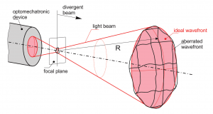
The focused spot produced by the mechatronic device can be examined by analyzing the resulting spherical wavefront.
One approach to derive the optical aberrations of an optical system is to measure the surface geometry of single components by surface profilers such as deflectometers, interferometers and tactile or non-tactile measuring machines, determining their relative alignment within the optical path and make use of simulation tools to obtain the aberrations of the entire optical system. With an increasing number of involved optical components, this approach becomes complex, time-consuming and does not allow a direct characterization of the optical quality after assembling the entire optical system.
Instead, measuring the wavefront of the focused beam emitted by the optical system allows to directly characterize the optical aberrations of the entire system, as depicted in Figure 1. A wavefront describes a surface composed of points of equal phase of the optical field within an optical wave. Each component inside the optical path contributes to the shape of the wavefront that can be measured by wavefront sensing devices. To determine the optical aberrations of the system, the measured wavefront is then compared to an ideal, aberration-free wavefront. Wavefront sensing is currently used in a whole variety of applications such as:
- optical shop testing to determine the quality of lenses,
- measuring the dynamic deformation of surfaces such as scanning mirrors,
- in production lines to characterize the surface topology of wafers, flat panels and glass sheets,
- in astronomy as part of a closed loop system to improve image quality, and
- in medical imaging for determining eye aberrations.
Scanning wavefront sensor
The research in this area also deals with a fundamental aspect of optics: The problem of directly assessing the shape of a light wave. The available tools – optical devices themselves – are not yet fit to deal with curved wavefronts. To overcome the limitations of the available sensor types they are integrated with high-precision positioning systems. By merging the wavefront data with the corresponding positioning and alignment data, a representation of the global wavefront can be achieved. The development of suitable reconstruction and stitching methods forms another central challenge of this research project.
Figure 2 depicts an experimental setup to investigate the properties of a scanning wavefront sensor. By repositioning and reorienting the sensor, its limitations concerning the opening angle of the wavefront under test can be circumvented.
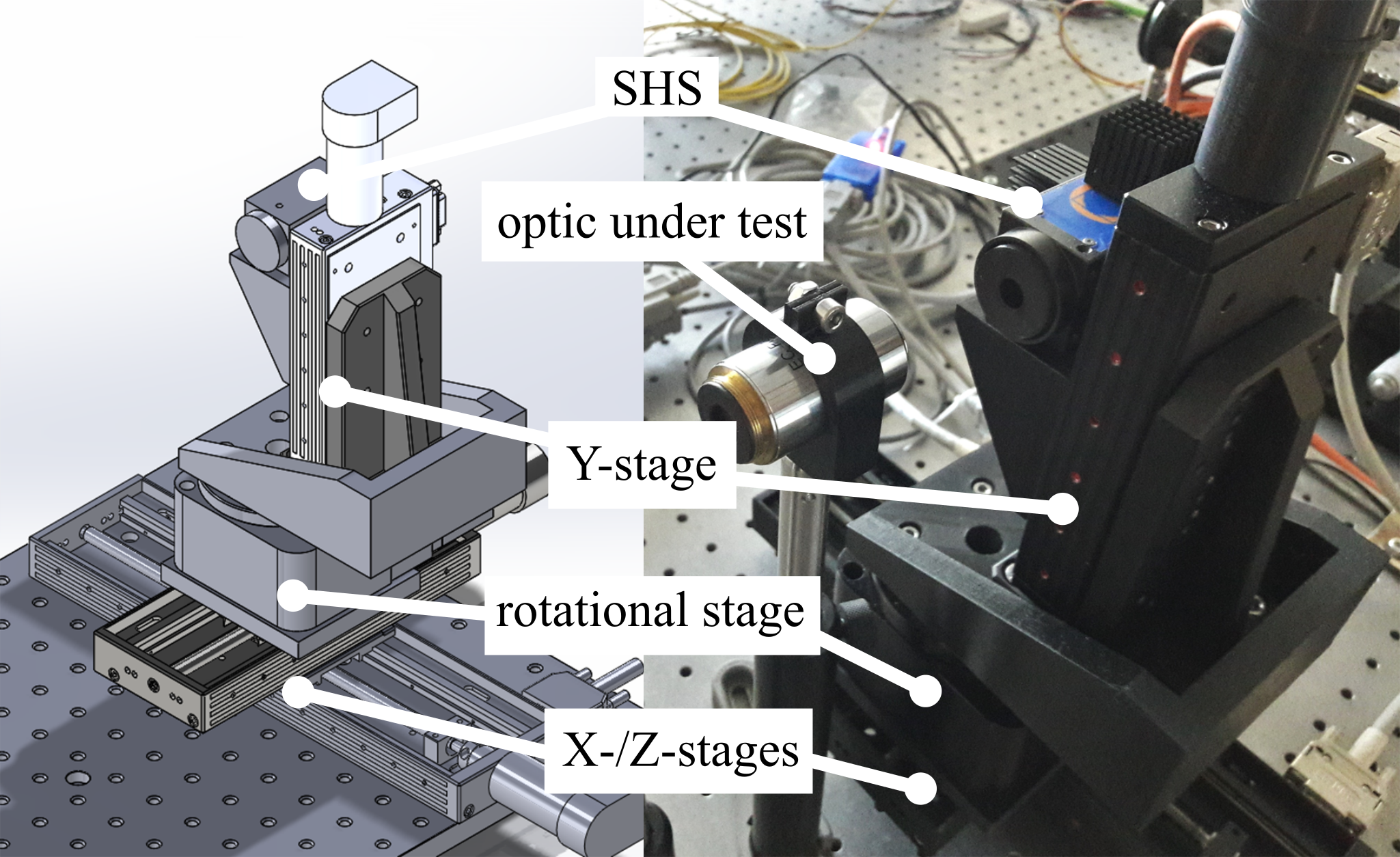
Shack-Hartmann sensor on a scanning setup.
Wavefront Reconstruction
With such a setup, a more or less arbitrary wavefront can be recorded by taking multiple, partially overlapping measurements. These measurements then have to be combined with the position data to form a representation of the global wavefront. Figure 3 shows a representation of such a curved wavefront which could not be acquired directly with a single, static sensor.
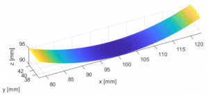
3D representation of a highly-divergent wavefront, reconstructed from 15 individual, partially overlapping measurements.
However, due to several positioning errors the sensor positions might be faulty which leads to a challenge of reconstructing the entire wavefront. Hence, sophisticated wavefront reconstruction algorithms have to be developed in order to get a well reconstructed wavefront despite these errors. Such algorithms mainly utilize estimation methods and digital image processing techniques like stitching, feature detection etc.
To facilitate the development of such algorithms a software that simulates the wavefront measurement with a Shack-Hartmann sensor is developed too (Figure 4).
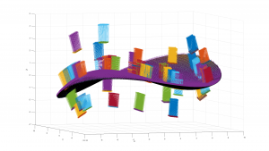
Simulation of measurement of a wavefront with a scanning Shack-Hartmann sensor.
Applications
- Characterization of freeform optical parts (e.g. modern smartphone lenses)
- Automatic characterization of optical components or assemblies
- In-line quality assurance