23.10.2019 Sasha
The assistance-robot Sasha, made by Toyota, has the typename HSR, standing for „Human Support Robot“. He is used both in private and industrial surroundings. His purpose is to keep order. Therefore he has to detect and assign objects. This is possible through the wide-angle and stereo cameras. His Laser Range Sensor helps with his orientation. The V4R-Team works on improving the image processing, the object recognition and the grasping for objects. A Robot able to manage similar tasks is called Kenny, developed by the V4R-Team within the SQUIRREL Project.
FUNDING:
Company Funding
23.10.2019 Aeolus
The goal of the project with Aeolus is to advance current robotic capabilities to pick up unknown objects in conditions of clutter and fetching known objects, with emphasis on the diversity of objects addressed, and on the reliability of grasping. During object pick-up, the robot may not need to maintain a constraint on the pose of grasped objects, while for fetching known objects includes delivering them to a human user while maintaining constraints on object pose. Part of the project is also to acquire object models through interaction with a person, finding, remembering and updating the location of objects in a home-like environment, and physically executing the fetch and object transfer.
FUNDING:
Company Funding
09.10.2019 InDex
Robot In-hand Dexterous manipulation by extracting data from human manipulation of objects to improve robotic autonomy and dexterity
The InDex project aims to understand how humans perform in-hand object manipulation and to replicate the observed skilled movements with dexterous artificial hands, merging the concepts of deep reinforcement and transfer learning to generalise in-hand skills for multiple objects and tasks. In addition, an abstraction and representation of previous knowledge will be fundamental for the reproducibility of learned skills to different hardware. Learning will use data across multiple modalities that will be collected, annotated, and assembled into a large dataset. The data and our methods will be shared with the wider research community to allow testing against benchmarks and reproduction of results. The core objectives are: (i) to build a multi-modal artificial perception architecture that extracts data of object manipulation by humans; (ii) the creation of a multimodal dataset of in-hand manipulation tasks such as regrasping, reorienting and finely repositioning; (iii) the development of an advanced object modelling and recognition system, including the characterisation of object affordances and grasping properties, in order to encapsulate both explicit information and possible implicit object usages; (iv) to autonomously learn and precisely imitate human strategies in handling tasks; and (v) to build a bridge between observation and execution, allowing deployment that is independent of the robot.
FUNDING:
The project is funded by FWF – Austrian Science Foundation & CHIST-ERA.


09.10.2019 HEAP
Human-Guided Learning and Benchmarking of Robotic Heap Sorting
In HEAP we focus on advancing the state-of-the-art for sorting a heap of unknown, irregular objects and provide appropriate benchmarks. In our scenarios, we deal with unknown, broken or deformed object instances such as concrete, metal pipes and other plastic/metal parts of possibly complex shape. A major goal of this project is to make challenging manipulation tasks easily accessible and reproducible, and to allow for a comparative evaluation of different approaches using a standardized robotic platform and an open source simulation framework. Our intention in providing such a benchmark framework is to (i) evaluate state-of-the-art grasping and manipulation algorithms in these complex heap sorting setups and (ii) to define new challenges in terms of object recognition and manipulation that need to be solved by the community.
FUNDING:
The project is funded by FWF – Austrian Science Foundation & CHIST-ERA.
04.10.2019 BURG
Benchmarks for Understanding Grasping
In the BURG Project we set out to boost grasping research by focusing on complete tasks and the related object manipulation constraints. In doing so, we need to move from objects to parts, since object parts facilitate the interpretable usage of objects. Parts are essential to know how and where the gripper can grasp given the constraints imposed by the task, e.g., pouring from a container implies grasping from the side. The novelty will come from learning to predict plausible grasps and to link grasps to the parts responsible for selecting each of them. In BURG we will boost grasping research by focusing on complete tasks and the related object manipulation constraints. In doing so, we need to move from objects to parts (Fig. 1), since object parts facilitate the interpretable usage of objects. Parts are essential to know how and where the gripper can grasp given the constraints imposed by the task, e.g., pouring from a container implies grasping from the side. The novelty will come from learning to predict plausible grasps and to link grasps to the parts responsible for selecting each of them.
FUNDING:
The project is funded by FWF – Austrian Science Foundation & CHIST-ERA.
05.11.2018 RoboCoop
Robotics Education driven by Interregional Cooperation
In schools and universities, there is at this moment a lack of interest in the MINT subjects (mathematics, informatics, natural sciences and technology) and in well-trained teachers for these subjects in Austria and Slovakia. Women, in particular, are clearly underrepresented in the MINT areas. This leads to bottlenecks in the job market, although there is an increasing demand for MINT personnel in the whole region. Robotics in education has proven to be a valuable tool for practical learning, not only for robotics itself, but for MINT topics in general. RoboCoop is a unique project aimed at exploiting the multidisciplinary potential of robotics and establishing cross-border educational activities to raise interest in MINT issues.
In RoboCoop, more than 4000 pupils, students and innovative MINT educators will be encouraged and engaged at interregional level to serve as a positive example of a wider use at national level in the two countries. To this end, 2 x 4 hours of workshops will be held at ACIN in which students will get to know the world of robots and foster their creativity and collaboration skills. The didactic concept alternates between instructive and constructive elements. In addition, a comprehensive quantitative and qualitative evaluation of all project activities should lead to policy recommendations in order to ensure a systematic and long-term implementation of the project ideas and thus to an early introduction of robotics topics at secondary level.
Partners:
TU Wien – Fakultät für Elektrotechnik und Informationstechnik
ACIN Institut für Automatisierungs- und Regelungstechnik
PRIA – Practical Robotics Institute Austria
SSR Wien – Stadtschulrat Wien
SUK – Slovak University of Technology in Bratislava
CVTI SR – Slovak Centre of Scientific and Technical Information
FUNDING:
The project is funded by the cooperation programme Interreg V-A SK-AT with the project number V212.


24.11.2017 iBridge
The iBridge project is a cross-generational project aimed at increasing the interest of children and pupils in the social and cross-cultural research topics and innovation as well as deepening their relationship to science through the application of robotics in the elderly care technologies. For these purposes the children and pupils will develop innovative “sensitive cuddly animal” as well as other service robots concepts, already well proven in the elderly care. Additionally, the pupils will support the older generation by providing access to modern technologies through PC / internet courses, learning and paying attention to their needs.
28.08.2017 Modeling and optimal control of electric machines with redundant stator windings
Project focus
- Modeling of PMSM with redundant stator windings
- Detection of failures of the PMSM
- Optimal fail-safe control of PMSM with redundant stator windings
Description
Permanent magnet synchronous machines (PMSM) are used in numerous industrial and automotive applications due to their high power to size ratio. In some of these applications (e.g., electric power steering systems), a fault of the motor (e.g., short circuit of stator windings or open connection of the stator coils), the inverter or the sensors (position or current sensor) can yield an undesired and even potentially dangerous behavior. To allow for an operation of the PMSM even in case of a fault, constructions with redundant stator windings and inverter legs have been proposed in literature, see, e.g. Fig. 1. Although there is a large variety of possible motor constructions, the main idea is to have more than three stator phases which are controlled by independent inverter legs. This allows for an operation, probably with decreased performance, of the PMSM in case of a single fault. Moreover, utilizing a position estimation strategy for PMSMs without a dedicated position sensor gives a fall back solution in case of a position sensor fault.
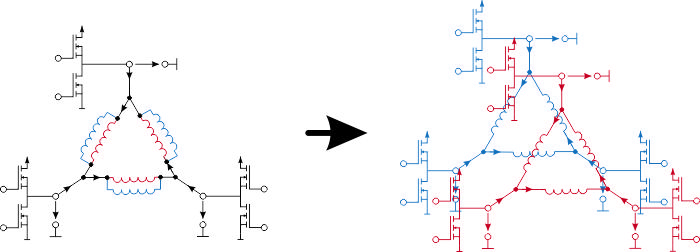
Setup of the stator windings with a single three-phase and a dual three-phase system
The majority of fail-safe control strategies and sensorless position estimation methods are based on a magnetically linear fundamental wave dq-model of the PMSM. In this research cooperation with Robert Bosch GmbH, strategies for the fault detection, the fail-safe operation and the optimal (position sensorless) control of permanent magnet synchronous machines with redundant stator windings are developed, which are capable to systematically take into account magnetic saturation and non-fundamental wave characteristics of the magnetic field. The basis for the design is a description of the PMSM by magnetic equivalent circuits, which allow to derive models of moderate complexity suitable for the analysis and the controller design. The resulting estimation and control strategies are intended to be utilized in automotive applications, as, e.g., electric power steering systems or electric drive trains.
Project partners
25.08.2017 Modeling and control of injection molding machines
Project focus
- Model-based design of optimal control strategies for the injection and holding pressure phase
- Model-based control of the temperature distribution in injection molding machines
- Application to injection molding machines with hydraulic direct drives
Description
Injection molding is the most prominent way to produce components made of plastics. In the injection molding process, plastics is liquefied by means of heating and deformation of the granulate. The liquid plastics is accumulating in the screw antechamber. If the screw is moved forward, the liquid fluid is injected into the mold. After sufficiently cooling down, the final plastics part can be taken out of the mold and the process can begin again.
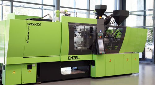
Photo of an injection molding machine
To obtain a high product quality during production, the stability of the injection process from one injection cycle to the next is of outmost importance. The main process variables in injection machines are the temperatures, the injection velocities and the injection pressures. Suitable control strategies are therefore necessary to obtain exact and reproducible tracking of the desired values for these quantities. In this research project in cooperation with Engel, optimal control strategies are developed for the injection and holding pressure phase (velocity, pressure) as well as the temperature for injection molding machines. One focus of this project lies on hydraulic actuated injection molding machines with hydraulic direct drive (servo-pump), which feature an improved energy efficiency compared to valve controlled machines. The control of these machines is particularly demanding due to the reduced dynamics of the actuation system.
Project partners
24.08.2017 Modeling and optimal control of permanent magnet synchronous motors
Project focus
- Magnetic equivalent circuit modeling of permanent magnet synchronous motors (PMSM)
- Systematic incorporation of magnetic saturation and non-sinusoidal field characteristics
- Optimal torque control
- Sensorless methods for the position estimation of PMSM
Description
Permanent magnet synchronous motors (PMSM) are applied in many industrial applications as e.g. robotics due to their high torque capabilities and their high energy efficiency. Field-oriented control is the industrial standard for the control of PMSMs. This control strategy is based on a transformation of the angle-dependent quantities of the PMSM on a dq0-coordinate frame which is fixed with the rotor. The design is typically based on the assumption of magnetic linearity and sinusoidal field characteristics of the PMSM.
Modern motor constructions frequently apply single tooth windings and an inhomogeneous air gap. This results in PMSMs where the assumption on a sinusoidal field characteristics is more or less violated. Moreover, PMSM are frequently operated up to regions with significant magnetic saturation. Thus, the assumption of the classical field-oriented control are frequently more or less violated in many practical applications.
In this research cooperation with Bernecker and Rainer Industrieelektronik GmbH (B&R), methods for systematic mathematical description of PMSMs with pronounced magnetic saturation and non-sinusoidal field characteristics are examined. Here, the magnetic equivalent circuit modeling (MEC) approach, which is based on an approximation of the magnetic system of the PMSM by magnetic resistances (reluctances) and magneto-motive force-sources (coils, permanent magnets), see Fig. 1.
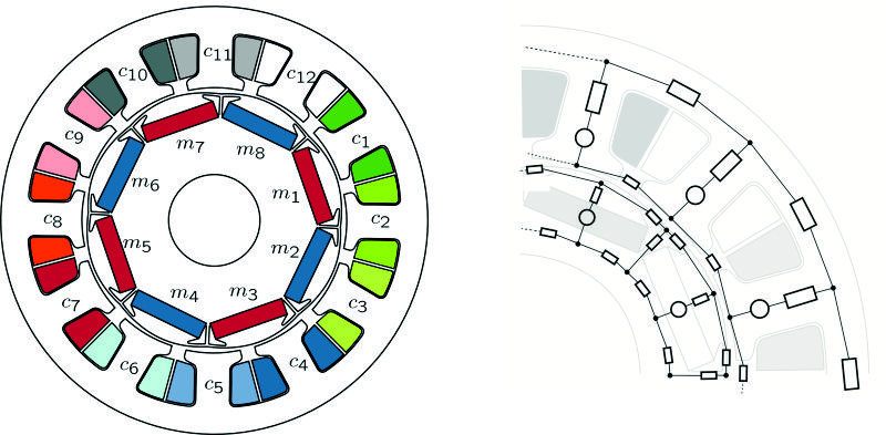
Cross-sectional view and possible magnetic equivalent circuit of a typical PMSM
Network theory, which is well known from electric circuits, is utilized to systematically obtain the mathematical model for arbitrary motor construction with rather complex magnetic equivalent networks, see, e.g., Fig. 2. Moreover, it is easily possible to systematically include magnetic saturation and non-sinusoidal field characteristics.
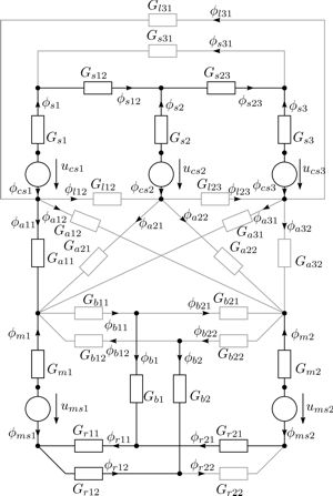
Magnetic equivalent circuit of a typical PMSM
The resulting MEC-models feature a rather low model complexity, which makes them suitable for a model-based design of control strategies. In this research project optimal control strategies for the indirect torque control of PMSMs, while minimizing the losses of the PMSM at the same time, are developed. These control strategies allow to significantly improve the torque control accuracy in comparison to a classical field oriented control strategy (dq), see, e.g., Fig. 3.
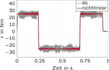
Torque control accuracy of the proposed optimal control strategy in comparison to a field-oriented control (dq)
The model-based approach allows to easily adopt the control strategies to other construction sizes and types of PMSMs. In particular, the control strategies can also be applied to linear motors. Moreover, the developed mathematical models are a good basis for the sensorless estimation of the position of PMSM.
Selected publications
- D. Faustner, W. Kemmetmüller, and A. Kugi, Flatness-Based Torque Control of Saturated Surface-Mounted Permanent Magnet Synchronous Machines, IEEE Transactions on Control Systems Technology, vol. 24, iss. 4, p. 1201–1213, 2016.
[BibTex] [Download]@Article{Faustner16, Title = {Flatness-Based Torque Control of Saturated Surface-Mounted Permanent Magnet Synchronous Machines}, Author = {Faustner, D. and Kemmetm{\"u}ller, W. and Kugi, A.}, Journal = {IEEE Transactions on Control Systems Technology}, Pages = {1201--1213}, Volume = {24}, Year = {2016}, Number = {4}, Doi = {10.1109/TCST.2015.2501345}, ISSN = {1063-6536}, } - D. Faustner, W. Kemmetmüller, and A. Kugi, Experimental Parameterization of a Design Model for Flatness-Based Torque Control of a Saturated Surface-Mounted PMSM, in Proceedings of the 7th IFAC Symposium on Mechatronic Systems & 15th Mechatronics Forum International Conference, Loughborough, UK, 2016, p. 575–582.
[BibTex]@InProceedings{Faustner16a, author = {Faustner, D. and Kemmetm\"uller, W. and Kugi, A.}, title = {Experimental Parameterization of a Design Model for Flatness-Based Torque Control of a Saturated Surface-Mounted PMSM}, booktitle = {Proceedings of the 7th IFAC Symposium on Mechatronic Systems \& 15th Mechatronics Forum International Conference}, year = {2016}, volume = {49}, number = {21}, month = {9}, pages = {575--582}, doi = {10.1016/j.ifacol.2016.10.663}, address = {Loughborough, UK}, issn = {2405-8963}, } - D. Faustner, W. Kemmetmüller, and A. Kugi, Magnetic Equivalent Circuit Modeling of a Saturated Surface-Mounted Permanent Magnet Synchronous Machine, in Proceedings of the 8th Vienna International Conference on Mathematical Modelling (MATHMOD), Vienna, Austria, 2015, p. 360–365.
[BibTex]@InProceedings{Faustner15, author = {Faustner, D. and Kemmetm\"uller, W. and Kugi, A.}, title = {Magnetic Equivalent Circuit Modeling of a Saturated Surface-Mounted Permanent Magnet Synchronous Machine}, booktitle = {Proceedings of the 8th Vienna International Conference on Mathematical Modelling (MATHMOD)}, year = {2015}, month = {2}, pages = {360--365}, doi = {10.1016/j.ifacol.2015.05.033}, address = {Vienna, Austria}, } - D. Faustner, W. Kemmetmüller, and A. Kugi, Field Weakening in Flatness-Based Torque Control of Saturated Surface-Mounted Permanent Magnet Synchronous Machines, in Proceedings of the 2015 IEEE Conference on Control Applications (CCA), Sydney, Australia, 2015, p. 858–863.
[BibTex]@InProceedings{Faustner15a, author = {Faustner, D. and Kemmetm\"uller, W. and Kugi, A.}, title = {Field Weakening in Flatness-Based Torque Control of Saturated Surface-Mounted Permanent Magnet Synchronous Machines}, booktitle = {Proceedings of the 2015 IEEE Conference on Control Applications (CCA)}, year = {2015}, publisher = {IEEE}, month = {9}, pages = {858--863}, doi = {10.1109/CCA.2015.7320725}, address = {Sydney, Australia}, } - W. Kemmetmüller, D. Faustner, and A. Kugi, Optimale Nichtlineare Regelung von permantenterregten Synchronmaschinen, at – Automatisierungstechnik, vol. 63, iss. 9, p. 739–750, 2015.
[BibTex] [Download]@Article{Kemmetmueller15a, Title = {Optimale Nichtlineare Regelung von permantenterregten Synchronmaschinen}, Author = {Kemmetm\"uller, W. and Faustner, D. and Kugi, A.}, Journal = {at -- Automatisierungstechnik}, Pages = {739--750}, Volume = {63}, Year = {2015}, Number = {9}, Doi = {10.1515/auto-2015-0041}, } - W. Kemmetmüller, D. Faustner, and A. Kugi, Optimal torque control of permanent magnet synchronous machines using magnetic equivalent circuits, Mechatronics, vol. 32, p. 22–33, 2015.
[BibTex] [Download]@Article{Kemmetmueller15b, Title = {Optimal torque control of permanent magnet synchronous machines using magnetic equivalent circuits}, Author = {Kemmetm\"uller, W. and Faustner, D. and Kugi, A.}, Journal = {Mechatronics}, Pages = {22--33}, Volume = {32}, Year = {2015}, Doi = {10.1016/j.mechatronics.2015.10.007}, ISSN = {0957-4158}, } - W. Kemmetmüller, D. Faustner, and A. Kugi, Modeling of a permanent magnet synchronous machine with internal magnets using magnetic equivalent circuits, IEEE Transactions on Magnetics, vol. 50, iss. 6, 2014.
[BibTex] [Download]@Article{Kemmetmueller14, Title = {Modeling of a permanent magnet synchronous machine with internal magnets using magnetic equivalent circuits}, Author = {Kemmetm{\"u}ller, Wolfgang and Faustner, David and Kugi, Andreas}, Journal = {IEEE Transactions on Magnetics}, Volume = {50}, Year = {2014}, Number = {6}, Doi = {10.1109/TMAG.2014.2299238}, }