15.05.2017 Soft Landing Strategien für elektromagnetische Schnellschaltventile
Projektschwerpunkte
- Zeitoptimaler Steuerungsentwurf zur Minimierung der Aufprallgeschwindigkeit des Ventilankers
Beschreibung
Der steigende Kostendruck auf mechatronische Produkte in der Fluidtechnik verlangt nach pneumatischen und hydraulischen Systemen, die mithilfe von günstigen und zuverlässigen elektromagnetischen Ventilen gesteuert werden können. Beispielhaft sei erwähnt, dass zunehmend bei der Servoregelung von Kolbenzylindern das kostenintensive Proportional-Wegeventil durch eine pneumatische/hydraulische Vollbrücke, bestehend aus kostengünstigen schnellschaltenden Ventilen, ersetzt wird. In anderen industriellen Anwendungen, wie beispielsweise in der Lebensmittelindustrie, werden schnellschaltende Wegeventile für Sortieraufgaben eingesetzt, mit immer höheren Anforderungen hinsichtlich der Taktzeiten und der Lebensdauer. Elektromagnetische Ventile in diesen Anwendungen müssen also schnelle Ventilschaltzeiten aufweisen, um eine hohe Bandbreite bzw. einen maximalen Durchsatz zu erreichen. Gleichzeitig muss für den Ventilanker garantiert werden, dass dieser zur Verringerung der Geräuschentwicklung bzw. des Verschleißes von mechanischen Komponenten mit einer minimalen Aufprallgeschwindigkeit in den Endanschlag prellt.
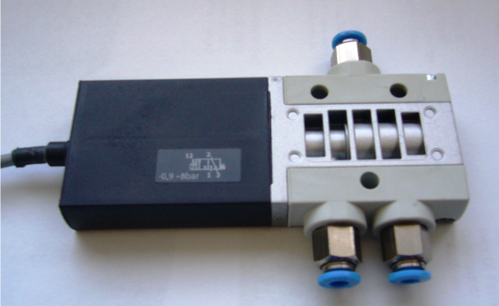
Schnellschaltventil.
Ziel dieser Arbeit ist es daher, eine Steuerstrategie zu entwickeln, die das zeitoptimale Schalten von elektromagnetischen Schnellschaltventilen mit minimaler Aufprallgeschwindigkeit des Ventilankers ermöglicht.
Ein Entwurf einer Steuerung für das zeitoptimale Schalten von elektromagnetischen Schnellschaltventilen mit minimaler Aufprallgeschwindigkeit des Ventilankers in den Endanschlag erfolgt anhand der Formulierung eines eingangsbeschränkten, zeitoptimalen Optimalsteuerungsproblems für die Punkt-zu-Punkt-Bewegung des Ventilankers. Hierzu wurde ein konzentriertparameterisches Ventilmodell hergeleitet und der quasi-zeitoptimale sowie der zeitoptimale Fall näher untersucht. Neben der numerischen Lösung des quasi-zeitoptimalen Optimalsteuerungsproblems anhand einer Volldiskretisierung wird durch Anwendung des Maximumsprinzips von Pontryagin das eingangsbeschränkte, quasi-zeitoptimale und zeitoptimale Optimalsteuerungsproblem in ein äquivalentes Zweipunktrandwertproblem umgeformt. In dieser Darstellung ist direkt ersichtlich, dass die eingangsbeschränkte und zeitoptimale Lösung für das Öffnen und Schließen des Ventils eine bang-singular-bang Steuerung ist.
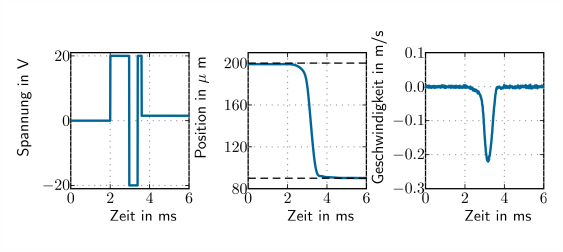
Optimale Trajektorie für das Öffnen des Ventils.
Messergebnisse an einem Versuchsstand bestätigen die theoretischen Ergebnisse und zeigen die Anwendbarkeit der vorgestellten Methodik. Abb. 1 zeigt dazu exemplarisch die bang-bang Steuerung für das öffnen und die resultierende Position und Geschwindigkeit des Ventilankers. Die Steuerstrategie wird für die Serie weiterentwickelt und es ist geplant, diese in das Produkt zu integrieren.
Ausgewählte Veröffentlichungen
- T. Glück, W. Kemmetmüller, A. Pfeffer, and A. Kugi, Pneumatic pulse-width modulated pressure control via trajectory optimized fast-switching electromagnetic valves, in Proceedings of the 13th Mechatronics Forum, Linz, Austria, 2012, p. 692 – 699.
[BibTex] [Download]@InProceedings{Gluck12, author = {T. Gl{\"u}ck and W. Kemmetm{\"u}ller and A. Pfeffer and A. Kugi}, title = {{Pneumatic pulse-width modulated pressure control via trajectory optimized fast-switching electromagnetic valves}}, booktitle = {Proceedings of the 13th Mechatronics Forum}, year = {2012}, month = {9}, pages = {692 -- 699}, address = {Linz, Austria}, } - T. Glück, W. Kemmetmüller, and A. Kugi, Trajectory optimization for soft landing of fast-switching electromagnetic valves, in Proceedings of the 18th IFAC World Congress, Milano, Italia, 2011, p. 11532–11537.
[BibTex] [Download]@InProceedings{Glueck11b, author = {T. Gl\"uck and W. Kemmetm\"uller and A. Kugi}, title = {{T}rajectory optimization for soft landing of fast-switching electromagnetic valves}, booktitle = {Proceedings of the 18th IFAC World Congress}, year = {2011}, month = {8}, pages = {11532--11537}, doi = {10.3182/20110828-6-IT-1002.01822}, address = {Milano, Italia}, }
Anwendungsbereiche
- Pneumatische Antriebstechnik
- Lebensmittelindustrie
15.05.2017 Thermisches Modell und optimale Zeitplanung des Warmwalzens
Projektschwerpunkte
- Modellierung der Abkühlung des Walzguts während des Warmwalzens
- Beobachterentwurf basierend auf Pyrometermessungen
- Optimierte Planung von Prozesszeiten
Beschreibung
Bei der Produktion von Grobblechen ist es von großer Bedeutung, die aktuelle Temperatur des Produkts zu kennen und durch angepasste Prozesszeiten genau einzustellen. Die Temperaturentwicklung ist entscheidend für den Produktionsprozess, weil viele mechanische Eigenschaften des Produkts, wie z.B. die Fließspannung, von der Temperatur abhängen. Außerdem werden die Mikrostruktur und damit wichtige Materialeigenschaften des Endprodukts von der Temperaturhistorie beeinflusst.
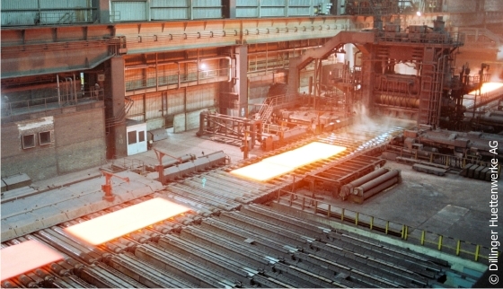
Walzwerk für Grobbleche, Copyright: Dillinger Hüttenwerke AG.
Während des Warmwalzens wirken sich die Prozessschritte auf die Temperatur des Walzgutes unterschiedlich aus: Einerseits kühlt die Walztafel an der Luft oder durch Kontakt mit Wasser und den Arbeitswalzen ab, andererseits führt die Deformation in den Walzstichen zu einer Erhöhung der Temperatur. Diese verschiedenen Effekte müssen von einem Temperaturmodell erfasst werden.
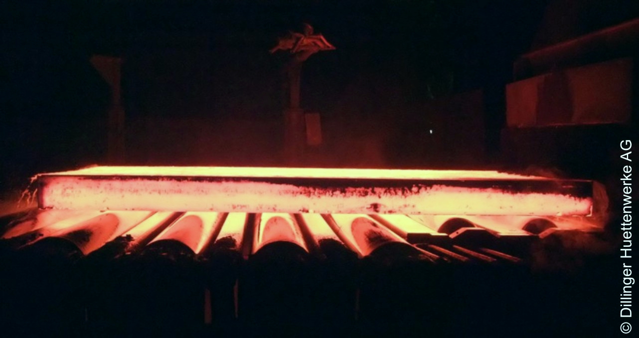
Verzunderte Bramme auf dem Rollgang, © Dillinger Hüttenwerke AG.
Mit Hilfe des Temperaturmodells können die Wartezeiten zur Erreichung der gewünschten Walztemperaturen vor jedem Walzstich genauer berechnet werden. Dadurch kann nicht nur eine bessere Qualität des Endprodukts erzielt sondern auch der Produktionsablauf gestrafft werden, da die Wartezeiten besser geplant werden können.
Um Modellungenauigkeiten oder unerwartete Störungen ausgleichen zu können, kann außerdem aufbauend auf dem Temperaturmodell ein Beobachter entworfen werden, der anhand von Messungen der Produktoberflächentemperaturen die Temperaturvorhersagen des Modells korrigiert. Da Kontaktmessungen aufgrund der schwierigen Messbedingungen und der sich bewegenden Walztafeln nicht möglich sind, kann die Temperatur nur durch Pyrometer gemessen werden. Diese Pyrometermessungen sind allerdings nur an einzelnen Punkten außerhalb der Walzgerüste möglich. Die dadurch bedingten punktuellen Messungen stellen eine zusätzliche Herausforderung beim Beobachterentwurf dar.
Ausgewählte Veröffentlichungen
- F. Schausberger, K. Speicher, A. Steinboeck, M. Jochum, and A. Kugi, Two Illustrative Examples to Show the Potential of Thermography for Process Monitoring and Control in Hot Rolling, in Proceedings of the 4th IFAC Workshop on Mining, Mineral and Metal Processing (MMM), Oulu, Finland, 2015, p. 48–53.
[BibTex] [Download]@InProceedings{Schausberger15c, author = {Schausberger, F. and Speicher, K. and Steinboeck, A. and Jochum, M. and Kugi, A.}, title = {Two Illustrative Examples to Show the Potential of Thermography for Process Monitoring and Control in Hot Rolling}, booktitle = {Proceedings of the 4th IFAC Workshop on Mining, Mineral and Metal Processing (MMM)}, year = {2015}, volume = {48}, number = {17}, month = {8}, pages = {48--53}, doi = {10.1016/j.ifacol.2015.10.076}, address = {Oulu, Finland}, issn = {2405-8963}, } - K. Speicher, A. Steinboeck, A. Kugi, D. Wild, and T. Kiefer, A plate temperature model used for planning and online adaptation of the roll pass schedule in hot rolling, in Proceedings of METEC and 2nd European Steel Technology and Application Days (ESTAD), Düsseldorf, Germany, 2015.
[BibTex]@InProceedings{Speicher15, author = {Speicher, Katrin and Steinboeck, Andreas and Kugi, Andreas and Wild, D. and Kiefer, T.}, title = {A plate temperature model used for planning and online adaptation of the roll pass schedule in hot rolling}, booktitle = {Proceedings of METEC and 2nd European Steel Technology and Application Days (ESTAD)}, year = {2015}, month = {6}, address = {D{\"u}sseldorf, Germany}, } - K. Speicher, A. Steinboeck, A. Kugi, D. Wild, and T. Kiefer, Analysis and design of an Extended Kalman Filter for the plate temperature in heavy plate rolling, Journal of Process Control, vol. 24, iss. 9, p. 1371–1381, 2014.
[BibTex] [Download]@Article{Speicher14a, Title = {Analysis and design of an Extended Kalman Filter for the plate temperature in heavy plate rolling}, Author = {Speicher, K. and Steinboeck, A. and Kugi, A. and Wild, D. and Kiefer, T.}, Journal = {Journal of Process Control}, Pages = {1371--1381}, Volume = {24}, Year = {2014}, Number = {9}, Doi = {10.1016/j.jprocont.2014.06.004}, } - K. Speicher, A. Steinboeck, D. Wild, T. Kiefer, and A. Kugi, An integrated thermal model of hot rolling, Mathematical and Computer Modelling of Dynamical Systems, vol. 20, iss. 1, p. 66–86, 2014.
[BibTex] [Download]@Article{Speicher14, Title = {{An integrated thermal model of hot rolling}}, Author = {K. Speicher and A. Steinboeck and D. Wild and T. Kiefer and A. Kugi}, Journal = {Mathematical and Computer Modelling of Dynamical Systems}, Pages = {66--86}, Volume = {20}, Year = {2014}, Number = {1}, Doi = {10.1080/13873954.2013.809364}, } - K. Speicher, A. Steinboeck, and A. Kugi, Measurement Errors of Radiation Pyrometers, in Proceedings of Rolling 2013, Venezia, Italy, 2013, p. 1–12.
[BibTex]@InProceedings{Speicher13a, author = {K. Speicher and A. Steinboeck and A. Kugi}, title = {{{M}easurement {E}rrors of {R}adiation {P}yrometers}}, booktitle = {Proceedings of Rolling 2013}, year = {2013}, month = {6}, pages = {1--12}, address = {Venezia, Italy}, } - K. Speicher, A. Steinboeck, D. Wild, T. Kiefer, and A. Kugi, Estimation of plate temperatures in hot rolling based on an extended Kalman filter, in Proceedings of 15th IFAC Symposium on Control, Optimization and Automation in Mining, Mineral & Metal Processing, San Diego, USA, 2013, p. 409 – 414.
[BibTex]@InProceedings{Speicher13, author = {K. Speicher and A. Steinboeck and D. Wild and T. Kiefer and A. Kugi}, title = {{Estimation of plate temperatures in hot rolling based on an extended Kalman filter}}, booktitle = {Proceedings of 15th IFAC Symposium on Control, Optimization and Automation in Mining, Mineral \& Metal Processing}, year = {2013}, month = {8}, pages = {409 -- 414}, doi = {10.3182/20130825-4-US-2038.00006}, address = {San Diego, USA}, } - K. Speicher, A. Steinboeck, T. Kiefer, and A. Kugi, Modeling Thermal Shocks and Air Cooling Using the Finite Difference Method, in Proceedings MATHMOD 2012 Vienna, Wien, Austria, 2012, p. 364–368.
[BibTex]@InProceedings{Speicher12, author = {K. Speicher and A. Steinboeck and T. Kiefer and A. Kugi}, title = {{{M}odeling {T}hermal {S}hocks and {A}ir {C}ooling {U}sing the {F}inite {D}ifference {M}ethod}}, booktitle = {Proceedings MATHMOD 2012 Vienna}, year = {2012}, editor = {Troch, I. and Breitenecker, F.}, month = {2}, pages = {364--368}, doi = {10.3182/20120215-3-AT-3016.00064}, address = {Wien, Austria}, }
Anwendungsbereiche
- Automatisiertes Walzen
- Zeitmanagement von Abkühlprozessen
08.05.2017 Zeit- und Reihenfolgeoptimierung für ein Grobblechwalzwerk mit Anwärmöfen im Chargenbetrieb
Projektschwerpunkte
- Mathematische Modellierung von Anwärmöfen im Chargenbetrieb
- Zeitoptimale Ansteuerung von Anwärmöfen
- Optimale Zeitplanung von Erwärm,- Walz,- und Manipulationsprozessen
- Reihenfolgeoptimierung für einen finiten Produktionshorizont
Beschreibung
In der Halbleiterindustrie kommen bei Sputter-Prozessen reine Metalle und spezielle Metalllegierungen als Sputter-Targets zum Einsatz. An diese Targets werden strenge Qualitätsanforderungen im Hinblick auf Form, Gefügestruktur und Reinheit gestellt, um eine entsprechend hochwertige Halbleiterfertigung zu garantieren. Die Herstellung von Sputter-Targets, insbesondere aus Werkstoffen mit hohen Schmelzpunkten (z.B. Molybdän), erfolgt dabei oft durch Sintern und anschließende Warmumformung. Beim Sintern wird Metallpulver in eine Form gepresst und erhitzt. Die so erhaltenen Sinterplatten werden in Öfen wiedererwärmt und an einem Walzgerüst zu Flachprodukten (Target-Platten) umgeformt.
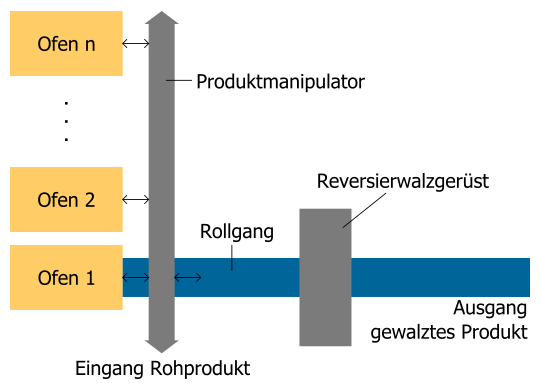
Anlagenübersicht.
Abbildung 1 zeigt eine Prinzipskizze der untersuchten Anlage. Die Anlage besteht aus mehreren Öfen mit unterschiedlichen Temperaturniveaus, einem Rollgang mit Reversierwalzgerüst und einem Produktmanipulator. Der Manipulator ist für alle Transporte der Produkte zwischen den Öfen und dem Rollgang zuständig. Die Erwärmung der Platten in den Öfen nimmt um ein Vielfaches mehr Zeit in Anspruch als die einzelnen Walzstiche. Zusätzlich sind zwischen den Walzstichen oft Zwischenerwärmungen vorgesehen. Da heiße Produkte nicht zwischengelagert werden können, muss die Verfügbarkeit der benötigten Anlagenteile zum jeweiligen Zeitpunkt stets garantiert sein. Die Produktivität der Anlage ist daher stark von den Ofenliegezeiten, sowie von der zeitlichen Verzahnung der Prozessschritte an den einzelnen Anlagenteilen abhängig. Ziel dieses Projekts ist es, einerseits die Ofenliegezeiten zu minimieren, und andererseits die Produktreihenfolge und die Startzeitpunkte der einzelnen Prozessschritte so zu wählen, dass die Anlage maximalen Durchsatz erzielt.
Als Grundlage für die Optimierung der Ofenliegezeiten wird ein thermisches Modell zur Simulation der Produkt- und Ofentemperaturen entwickelt. Abbildung 2 zeigt seinen formalen Aufbau. Dieses Simulationsmodell ermöglicht es, vorab minimale Heizzeiten zu berechnen und die Produkttemperatur während der Erwärmung im laufenden Betrieb mitzuschätzen. Die Aufheizzeit eines Produktes hängt stark von seiner Strahlungsemissivität ab, welche jedoch Unsicherheiten unterworfen ist. Das entwickelte System erzielt eine gute A-priori-Schätzung der Emissivität eines Produktes, indem es die Erwärmvorgänge früher erwärmter ähnlicher Produkte analysiert. Zu diesem Zweck werden die Produkte zu Gruppen zusammengefasst und die mittlere Emissivität innerhalb jeder Gruppe im Zeitverlauf geschätzt. Zusätzlich dient das entwickelte Modell als Entwurfsgrundlage einer modellbasierten zeitoptimalen Ofensteuerungsstrategie.
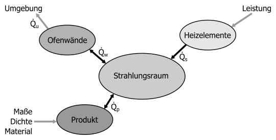
Thermische Modellierung der Öfen.
Des Weiteren wird ein Software-Werkzeug entwickelt, welches eine Optimierung der Produktreihenfolge und der Prozesszeiten vornimmt. Das zugrundeliegende NP-schwere kombinatorische Optimierungsproblem (Flexible Job Shop Scheduling Problem) wird zur Lösung in einen Teil zur Bestimmung der Prozesszeiten bei bekannter Produktreihenfolge und einen Teil zur übergeordneten Optimierung der Produktreihenfolge aufgeteilt. Die optimalen Prozesszeiten werden mit einem eigens entwickelten rekursiven Algorithmus ermittelt. Zur Optimierung der Produktreihenfolge kommen heuristische Methoden zum Einsatz. Da das Software-Werkzeug in Form einer rollierenden Planung mit einem finiten Planungshorizont ausgeführt wird, kann auf unvorhergesehene Änderungen des Produktionsprogrammes rasch reagiert werden.
Ausgewählte Publikationen
- A. Aschauer, F. Roetzer, A. Steinboeck, and A. Kugi, Efficient scheduling of a stochastic no-wait job shop with controllable processing times, Expert Systems with Applications, vol. 162, p. 113879, 2020.
[BibTex] [Download]@Article{Aschauer2020, author = {Aschauer, A. and Roetzer, F. and Steinboeck, A. and Kugi, A.}, title = {Efficient scheduling of a stochastic no-wait job shop with controllable processing times}, doi = {10.1016/j.eswa.2020.113879}, pages = {113879}, volume = {162}, journal = {Expert Systems with Applications}, month = {7}, year = {2020}, }
- F. Rötzer, A. Aschauer, L. Jadachowski, A. Steinboeck, and A. Kugi, Temperature Control for Induction Heating of Thin Strips, in Proceedings of the 21st IFAC World Congress, Berlin, Germany, 2020, p. 11968–11973.
[BibTex]@InProceedings{Roetzer2020, author = {F. R\"otzer and A. Aschauer and L. Jadachowski and A. Steinboeck and A. Kugi}, booktitle = {Proceedings of the 21st IFAC World Congress}, title = {Temperature Control for Induction Heating of Thin Strips}, doi = {10.1016/j.ifacol.2020.12.722}, note = {IFAC-PapersOnLine}, number = {2}, pages = {11968--11973}, volume = {53}, address = {Berlin, Germany}, issn = {2405-8963}, month = {06}, year = {2020}, }
- A. Aschauer, F. Roetzer, A. Steinboeck, and A. Kugi, Scheduling of a Flexible Job Shop with Multiple Constraints, in Proceedings of the 16th IFAC Symposium on Information Control Problems in Manufacturing INCOM, Bergamo, Italy, 2018, pp. 1293-1298.
[BibTex]@InProceedings{Aschauer2018, author = {Aschauer, A. and Roetzer, F. and Steinboeck, A. and Kugi, A.}, title = {Scheduling of a Flexible Job Shop with Multiple Constraints}, booktitle = {Proceedings of the 16th IFAC Symposium on Information Control Problems in Manufacturing INCOM}, year = {2018}, volume = {51}, number = {11}, month = {6}, pages = {1293-1298}, doi = {10.1016/j.ifacol.2018.08.354}, address = {Bergamo, Italy}, issn = {2405-8963}, }
- F. Rötzer, A. Aschauer, A. Steinboeck, and A. Kugi, A Computationally Efficient 3D Mathematical Model of a Molybdenum Batch-Reheating Furnace, in Proceedings of the 9th Vienna International Conference on Mathematical Modelling (MATHMOD), Vienna, Austria, 2018, p. 819–824.
[BibTex]@InProceedings{Roetzer2018, author = {R\"otzer, F. and Aschauer, A. and Steinboeck, A. and Kugi, A.}, title = {A Computationally Efficient 3D Mathematical Model of a Molybdenum Batch-Reheating Furnace}, booktitle = {Proceedings of the 9th Vienna International Conference on Mathematical Modelling (MATHMOD)}, year = {2018}, month = {2}, pages = {819--824}, doi = {10.1016/j.ifacol.2018.04.015}, address = {Vienna, Austria}, }
- A. Aschauer, F. Roetzer, A. Steinboeck, and A. Kugi, An Efficient Algorithm for Scheduling a Flexible Job Shop with Blocking and No-Wait Constraints, in Proceedings of the 20th IFAC World Congress, Toulouse, France, 2017, pp. 12490-12495.
[BibTex]@InProceedings{Aschauer17, author = {Aschauer, A. and Roetzer, F. and Steinboeck, A. and Kugi, A.}, title = {An Efficient Algorithm for Scheduling a Flexible Job Shop with Blocking and No-Wait Constraints}, booktitle = {Proceedings of the 20th IFAC World Congress}, year = {2017}, volume = {50}, number = {1}, month = {7}, pages = {12490-12495}, doi = {10.1016/j.ifacol.2017.08.2056}, address = {Toulouse, France}, issn = {2405-8963}, }
Anwendungsbereiche
- Walzwerksautomatisierung
- Industrieöfen
- Zeit- und Reihenfolgeoptimierung in Produktionsprozessen
Fördergeber
Diese Forschungsarbeiten sind Teil des EU-Projekts SemI40, welches durch das Programm ECSEL Joint Undertaking (Grant Agreement No. 692466) und durch das Programm „IKT der Zukunft“ (Projektnummer: 853343) des Bundesministeriums für Verkehr, Innovation und Technologie (bmvit) im Zeitraum von Mai 2016 bis April 2019 gefördert wird. Weiterführende Information zu IKT der Zukunft findet sich unter www.bmvit.gv.at/ikt.
 |
 |
24.02.2017 Automatisierte Handhabung biegeschlaffer Materialien
Projektschwerpunkte
- Prototypischer Aufbau eines Handhabungssystems für das automatisierte Handling von formlabilen Halbzeugen
- Untersuchung und Bewertung verschiedener Greifertechnologien
- Mathematische Modellierung des Zug- und Biegeverhaltens biegeschlaffer Kohlefaser-Halbzeuge
- Kontrollierte Vorgabe der Faserzugspannungen der Handhabungsobjekte durch Positions- und Kraftregelung
Beschreibung
Waren Faserverbundwerkstoffe noch vor einigen Jahren ausschließlich „High-End“-Anwendungen in der Luft- und Raumfahrt vorbehalten, so weisen diese, aufgrund ihres enormen Leichtbaupotenzials, auch zunehmend in den Bereichen Automotive, Maschinen- und Anlagenbau, etc. ein starkes Wachstum auf. Für eine branchenübergreifende Nutzung von Faserverbunden müssen allerdings die erheblichen Mehrkosten gegenüber traditionellen Materialien reduziert und gleichzeitig die notwendige Prozesssicherheit gewährleistet werden. Werden die Faserverbunde heute noch weitgehend in manuellen bzw. teilautomatisierten Verfahren hergestellt, geht die Richtung in eine flexible, durchgängige Industrialisierung vorhandener Produktionsprozesse. Dabei stellt insbesondere das (kontur)flexible Aufnehmen der trockenen bzw. teilimprägnierten Halbzeuge vom Schneide- bzw. Ablagetisch und das anschließende kontrollierte Ablegen in gegebene Formwerkzeuge große Herausforderung an die automatisierte Handhabungstechnik dar.
Obwohl bereits zahlreiche Arbeiten zur theoretischen Beschreibung des Zug- und Biegeverhaltens von Kohlefaser-Halbzeugen vorliegen, finden diese aufgrund der Modellkomplexität kaum Anwendung in der automatisierten Handhabung. Nach Stand der Technik wird das Handling der Materialien (zumeist) rein steuerungstechnisch (Stichwort: Teach-In) umgesetzt, d.h. man verzichtet auf jegliches Modellwissen und Rückkopplung durch eine geeignete Sensorik.
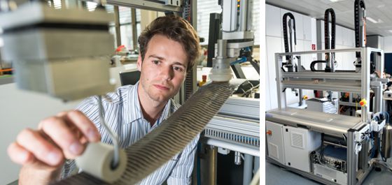
Versuchsaufbau zur automatisierten Handhabung biegeschlaffer Materialien
Im Rahmen dieses Projekts wird prototypisch ein Handhabungssystem aufgebaut und das Potential der modernen modellbasierten Regelungstechnik für die Handhabung biegeschlaffer Materialien, wie sie die Halbzeuge darstellen, untersucht.
Als Handhabungsobjekte werden Gewebe- und Gelegestreifen unterschiedlicher Fadenzahl, Bindung, Dicke und mit unterschiedlichem Flächengewicht untersucht. Für den punktuellen Kraftschluss zwischen Handhabungsobjekt und Greifsystem werden verschiedene Greifer betrachtet und nach deren Eignung für bestimmte Gewebekategorien bewertet. Die Modellparameter der unterschiedlichen Materialien werden im Zuge von einfachen Tests identifiziert und auf Basis des Modells das Deformationsverhalten simuliert. Der Fokus bei der mathematischen Modellierung wird auf eine regelungstechnische Umsetzung gelegt, d.h. es gilt eine echtzeitfähige Vorhersage des Deformationsverhaltens über eine große Materialklasse zu finden. Darauf aufbauend werden geeignete Strategien zu Kraft- und Positionsregelung entworfen. Die kontrollierte Vorgabe der Faserzugspannung während dem Handling ermöglicht eine sichere Aufnahme, die Beibehaltung der geometrischen Bestimmtheit während der Handhabung (keine Faserverschiebungen) und ein faltenfreies, materialschonendes Ablegen in bzw. auf komplexen Formen.
Die Thematik beschränkt sich dabei nicht nur auf das Handling von Kohlefaser-Halbzeugen. Die erarbeiteten Konzepte sind übertragbar auf zahlreiche andere Fragestellungen, wie zum Beispiel dem automatisierten Aufkleben von großflächigen Folien, der Handhabung von Textilien, etc.
Videos
Ausgewählte Veröffentlichungen
- S. Flixeder, Force-Based Cooperative Manipulation of Highly Deformable Materials, A. Kugi and K. Schlacher, Eds., Aachen: Shaker Verlag, 2017, vol. 36.
[BibTex]@Book{Flixeder17a, Title = {Force-Based Cooperative Manipulation of Highly Deformable Materials}, Author = {Flixeder, S.}, Editor = {A. Kugi and K. Schlacher}, Publisher = {Shaker Verlag}, Year = {2017}, Address = {Aachen}, Series = {Modellierung und Regelung komplexer dynamischer Systeme}, Volume = {36}, ISBN = {978-3-8440-5401-9}, Organization = {Institute f{\"u}r Automatisierungs- und Regelungstechnik (TU Wien) und Regelungstechnik und Prozessautomatisierung (JKU Linz)}, } - S. Flixeder, T. Glück, M. Böck, and A. Kugi, Model-Based Signal Processing for the Force Control of Biaxial Gantry Robots, in Proceedings of the 20th IFAC World Congress, Toulouse, France, 2017, p. 3208–3214.
[BibTex]@InProceedings{Flixeder17, author = {Flixeder, S. and Gl\"uck, T. and B\"ock, M. and Kugi, A.}, title = {Model-Based Signal Processing for the Force Control of Biaxial Gantry Robots}, booktitle = {Proceedings of the 20th IFAC World Congress}, year = {2017}, volume = {50}, number = {1}, month = {7}, pages = {3208--3214}, doi = {10.1016/j.ifacol.2017.08.439}, address = {Toulouse, France}, issn = {2405-8963}, } - S. Flixeder, T. Glück, and A. Kugi, Force-based cooperative handling and lay-up of deformable materials: Mechatronic design, modeling, and control of a demonstrator, Mechatronics, vol. 47, p. 246–261, 2017.
[BibTex]@Article{Flixeder16a, Title = {Force-based cooperative handling and lay-up of deformable materials: Mechatronic design, modeling, and control of a demonstrator}, Author = {Flixeder, S. and Gl\"uck, T. and Kugi, A.}, Journal = {Mechatronics}, Pages = {246--261}, Volume = {47}, Year = {2017}, Doi = {10.1016/j.mechatronics.2016.10.003}, ISSN = {0957-4158}, } - S. Flixeder, T. Glück, and A. Kugi, Modeling and Force Control for the Collaborative Manipulation of Deformable Strip-Like Materials, in Proceedings of the 7th IFAC Symposium on Mechatronic Systems & 15th Mechatronics Forum International Conference, Loughborough, UK, 2016, p. 95–102.
[BibTex] [Download]@InProceedings{Flixeder16, author = {Flixeder, S. and Gl\"uck, T. and Kugi, A.}, title = {Modeling and Force Control for the Collaborative Manipulation of Deformable Strip-Like Materials}, booktitle = {Proceedings of the 7th IFAC Symposium on Mechatronic Systems \& 15th Mechatronics Forum International Conference}, year = {2016}, volume = {49}, number = {21}, month = {9}, pages = {95--102}, doi = {10.1016/j.ifacol.2016.10.518}, address = {Loughborough, UK}, issn = {2405-8963}, } - S. Flixeder, T. Glück, M. Böck, R. Neumann, and A. Kugi, Kombinierte Pfad- und Nachgiebigkeitsregelung für ein Portalsystem mit experimenteller Validierung, in Tagungsband Mechatronik, Dortmund, Germany, 2015, p. 37–42.
[BibTex] [Download]@InProceedings{Flixeder15, author = {Flixeder, S. and Gl\"uck, T. and B\"ock, M. and Neumann, R. and Kugi, A.}, title = {{K}ombinierte {P}fad- und {N}achgiebigkeitsregelung f{\"u}r ein {P}ortalsystem mit experimenteller {V}alidierung}, booktitle = {Tagungsband Mechatronik}, year = {2015}, month = {3}, pages = {37--42}, address = {Dortmund, Germany}, } - S. Flixeder, T. Glück, M. Böck, and A. Kugi, Combined Path Following and Compliance Control with Application to a Biaxial Gantry Robot, in Proceedings of the IEEE Conference on Control Applications (CCA), Antibes, France, 2014, p. 796–801.
[BibTex] [Download]@InProceedings{Flixeder14, author = {Flixeder, Stefan and Gl\"uck, Tobias and B\"ock, Martin and Kugi, Andreas}, title = {Combined Path Following and Compliance Control with Application to a Biaxial Gantry Robot}, booktitle = {Proceedings of the IEEE Conference on Control Applications (CCA)}, year = {2014}, month = {10}, pages = {796--801}, doi = {10.1109/CCA.2014.6981438}, address = {Antibes, France}, } - S. Flixeder, T. Glück, M. Böck, and A. Kugi, Kombinierte Pfad- und Impedanzregelung für ein Portalsystem, in Tagungsband GMA-Fachausschuss 1.40 „Theoretische Verfahren der Regelungstechnik“, Anif/Salzburg, Austria, 2014, p. 128–154.
[BibTex]@InProceedings{Flixeder14a, author = {Flixeder, S. and Gl\"uck, T. and B\"ock, M. and Kugi, A.}, title = {Kombinierte {P}fad- und {I}mpedanzregelung f\"ur ein {P}ortalsystem}, booktitle = {Tagungsband GMA-Fachausschuss 1.40 "Theoretische Verfahren der Regelungstechnik"}, year = {2014}, month = {9}, pages = {128--154}, address = {Anif/Salzburg, Austria}, }
Anwendungsbereiche
- Luft- und Raumfahrt
- Automobilindustrie
- Maschinen- und Anlagenbau
Projektpartner und Förderung
08.06.2016 RALLI
Robotic Action-Language Learning through Interaction
Zukünftige soziale Roboter, die im Alltag eingesetzt werden sollen, benötigen die Fähigkeit, neue Aufgaben durch Beobachtung und Sprachinstruktionen zu meistern, insbesondere als nicht alle Umgebungsfaktoren und Eventualitäten vorimplementiert werden können. Daher beschäftigt sich RALLI mit dem Lernen neuer Aktionen in Verbindung mit entsprechenden sprachlichen Äußerungen. Durch die neu entwickelten Algorithmen, die auf entwicklungspsychologischen Studien zum Erwerb von Aktionsverben beruhen, soll der Roboter durch Beobachten und die Interpretation von menschlichen Aktionen deren grundlegende Aspekte, wie notwendige Bewegungstrajektorien und involvierte Objekte, identifizieren. Zeitgleich kann der Roboter die sprachliche Äußerung analysieren, die die Aktion beschreibt und deren syntaktische Elemente mit den semantischen Elementen der Aktions-Repräsentation verbinden. Dadurch ist der Roboter in der Lage über Verben und ihre Argumentstrukturen Aktionen zu lernen und umgekehrt.
Partner
Funding

08.06.2016 ACROSSING
Advanced TeChnologies and PlatfoRm fOr Smarter ASsisted LivING
ACROSSING is an innovative research training network funded by the EU H2020 Marie Sklodowska-Curie Actions programme which aims to change the way millions of the older people in Europe live and maintain wellbeing. The project aims to make a critical contribution towards an open smart home technology infrastructure by interlinking disciplines from sensing technologies, context inferences and interaction and considering key principles of social impact, ethics, security and privacy.
Scientific target:
Develop technologies for smart-home based assisted living, including 4 specialised technology infrastructures, a shared experiment data repository and guidelines for smart home development based on best-practice demonstrators.
Training target:
Educate 15 ESRs in multi-disciplinary, transferable skills to become future research leaders in assisted living and create networks for future collaborations among partners.
Social target:
Increase European innovation capacity and competitiveness in smart home technology through the collaboration of industry and academia by integrating 4 ICT-driven application demonstrators as best-practice examples for the envisioned open SH technology infrastructure.
Partners
De Monfort University Leicester
Universität Passau
Austrian Institute of Technology
Noldus Information Technology
Philips
Ingeniería y Soluciones Informáticas (ISOIN)
CERTH – Centre for Research & Technology Hellas
Ulster University
Universidad Politécnica de Madrid (UPM)
Funding
Marie Sklodowska-Curie EU Framework for Research and Innovation Horizon 2020
08.06.2016 RoboFit
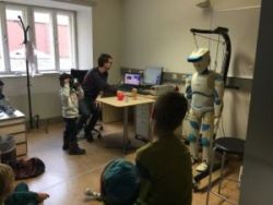
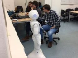
Im Projekt RoboFit besuchen uns Klassen (von Vorschulalter bis Oberstufe), um einen Vortrag über Robotik zu hören, bei einem kurzen Workshop sich an Roboternavigation zu versuchen, und um eine Demo unserer Roboter Romeo oder Pepper zu sehen. Außerdem stellen wir unser Wissen und unsere Erfahrung mit dem von uns entwickelten Schräge Roboter Konzept sowie mit der Durchführung von Benutzerstudien im Bereich Mensch-Roboter Interaktion dem Projekt zur Verfügung und betreuen vorwissenschaftliche Arbeiten im Bereich Robotik.
Projektteam
Prof. Markus Vincze ist der Öffentlichkeit als Robotikforscher bekannt. Zuletzt sorgten er und sein Team für Schlagzeilen mit HOBBIT, einem Roboter, der älteren Menschen ermöglichen soll, länger in ihrer eigenen Wohnung zu bleiben. Öffentlichkeitsprojekte wie z.B. die „Lange Nacht der Roboter“ oder die Mitarbeit bei der Roboterausstellung im Technischen Museum Wien sind wichtig, um der von Science-Fiction inspirierten breiten Masse zu zeigen, wie die Robotik in real aussieht und mit welchen Arbeiten sich derzeitige Roboterexperten wirklich beschäftigen.
Dr. techn. Lara Lammer ist eine kritische Denkerin, die verschiedene Ideen generiert, um die Probleme des 21. Jahrhunderts zu adressieren, um dann Lösungen mit anderen kreativen Köpfen zu konzipieren. Sie ist Projekleiterin, Kommunikatorin und Wissenschaftlerin in den Bereichen Robotik und Bildungsrobotik an der Technischen Universität Wien. Ihre wissenschaftliche Arbeit fokussiert sich auf holistische Konzepte und systemisches Denken. Sie hat das Konzept Schräge Roboter entwickelt und in verschiedenen Workshops (von Kindergarten bis Universität) angewandt, um junge Menschen in die Robotik aus der Perspektive der Produktentwicklung einzuführen.
Julian Angel, PhD, ist Experte in Mensch-Roboter Interaktion und entwickelt im EU Projekt ER4STEM (Educational Robotics for Science, Technology, Engineering and Mathematics) ein Framework und eine Plattform um diverse europäische Aktivitäten in der Bildungsrobotik unter einem Dach zu vereinen.
Clara Haider, Matthias Hirschmanner, Clemens Korner, Anvesh Nookala und Tobias Wolfmayr sind studentische Mitarbeiter, die das Projekt bei den Schulbesuchen, Workshops und Demos tatkräftig unterstützen.
Funding
FFG – Österreichische Forschungsförderungsgesellschaft
08.06.2015 AssistMe
AssistMe develops and evaluates during a user-centered multistage process innovative means of interaction for programming and usage of a robot-based assistive system.
Central topic is the integration of users in the concept development where the interaction paradigms are defined as well as in the evaluation stage of the developed technology. AssistMe examines the applicability of haptic (force feedback) interaction technology with means of machine vision respectively with methods from the field of spatial augmented reality. Together with two industrial companies universal applicability of the developed methodologeis will be evaluated in two entirely different application scenarios. One field of application is the assembly of automotive comustion engines while the other UseCase treats the machining (polishing) of casting modls.
Partners
Profactor (coordinator)
BMW Motoren GmbH
GPN GmbH
Funding
FFG – 7. Ausschreibung Produktion der Zukunft nat. Projekte
08.06.2015 ALOOF
Autonomous Learning of the Meaning of Objects
ALOOF wird es Robotern ermöglichen, die Bedeutung von Objekten zu erlernen, die sie noch nie zuvor gesehen haben. Dabei wird das stetig wachsende Wissen aus den Erfahrungen des Roboters und des Webs in einer für situierte Umgebungen geeigneten Wissensrepräsentation nutzbar gemacht. Durch gezielte Suche im Web werden Roboter lernen, welche spezifischen Eigenschaften Objekte haben, oder an welchen Orten man diese üblicherweise finden kann. Um dies zu ermöglichen brauchen Roboter einen Mechanismus, der es Ihnen ermöglicht, Wissen aus Erfahrung und Wissen aus dem Web zu fusionieren.
Das Ziel von ALOOF ist es, die Möglichkeiten autonomer Systeme zu erweitern, um deren Betrieb in stetig veränderlichen, dynamischen Umgebungen zu verbessern, indem diese kontinuierlich lernen, ihr Wissen über die Bedeutung von Objekten mithilfe von Internet Ressourcen zu erweitern.
Der Fokus in ALOOF ist hierbei explizit auf Objekte gerichtet und die damit auftretenden Wissenslücken, die ein Service-Roboter im Betrieb schließen muss.
Der grundlegende Beitrag von ALOOF ist es, Robotern zu ermöglichen, Repräsentationen ihrer situierten Erfahrung und jene im Web optimal zu kombinieren.
Partner
- University of Rome La Sapienza, Department of Computer, Control and Management Engineering “Antonio Ruberti”
- ALCOR – Vision, Perception and Learning Robotics Lab
Rome, Italy
Prof. Barbara Caputo - School of Computer Science, University of Birmingham, Birmingham, United Kingdom
Dr. Nick Hawes - INRIA Sophia Antipolis, Wimmics Team, France
Sophia Antipolis
Dr. Fabien Gandon - Technische Universität Wien
Vienna, Austria
Prof. Markus Vincze
Funding
Chist-era, FWF
08.06.2015 ER4STEM
Educational Robotics for STEM
Many children lose their natural curiosity for how things function and interrelate to each other along the way into their lives as young adults. The Educational Robotics for STEM (ER4STEM) project aims to turn curious young children into young adults passionate about science and technology with a hands-on use case: robotics. The domain of robotics represents a multidisciplinary and highly innovative field encompassing physics, maths, informatics and even industrial design as well as social sciences. Moreover, due to various application domains, teamwork, creativity and entrepreneurial skills are required for the design, programming and innovative exploitation of robots and robotic services. Children are fascinated by such autonomous machines. This fascination and the variety of fields and topics covered make robotics a powerful idea to engage with. Young girls as well as boys can easily connect robots to their personal interests and share their ideas through these tangible artefacts.
ER4STEM will refine, unify and enhance current European approaches to STEM education through robotics in one open operational and conceptual framework. The concept is founded on three important pillars of constructionism: 1. engaging with powerful ideas, 2. building on personal interests, and 3. learning through making (or presenting ideas with tangible artefacts). The ER4STEM framework will coherently offer students aged 7 to 18 as well as their educators different perspectives and approaches to find their interests and strengths in robotics to pursue STEM careers through robotics and semi-autonomous smart devices. At the same time students will learn about technology (e.g. circuits), about a domain (e.g. math) and acquire skills (e.g. collaborating, coding). Innovative approaches will be developed to achieve an integrated and consistent concept that picks children up at different ages, beginning in primary school and accompany them until graduation from secondary school.
Partners
- European Software Institute Center Eastern Europe
- Practical Robotics Institute Austria
- University of Athens Educational Technology Lab
- AcrossLimits
- Cardiff University School of Social Science
- Certicon
Funding
- EU H2020-SEAC-2014-1